Lab 7 - Topology - Custom Topology Hierarchy
We want to understand how to use the Topology Interface, modify the display, and understand how to modify one of the available Network Hierarchies provided.
Here is what we want the final display to be. We are focusing on the device roles and their placement in a Leaf/Spine architecture.
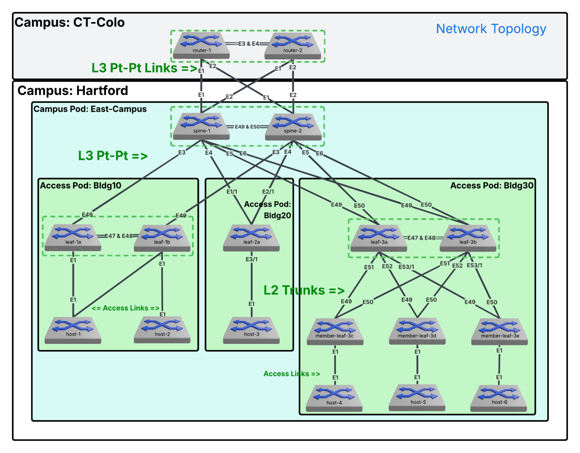
Here is what we want the final diagram to be.
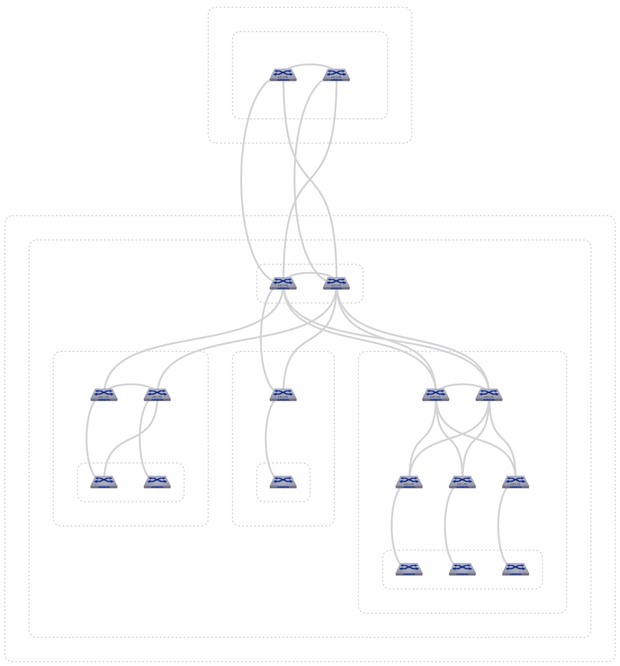
Final topology reference diagram.
Note* Topology Logic: Priority and Alignment
- Vertical Placement: "Who are you?" (The Priority Index)
- Topological Role Weighting. The engine applies a strict top-to-bottom hierarchical priority based on your role tags for specific strings and "weights" them accordingly:
- Highest Priority: core or super-spine
- High Priority: spine
- Low Priority: leaf
- Lowest Priority: host or endpoint
- Container Inheritance: A container assumes the vertical priority of the highest-tier node inside of it. A container holding a spine will always float above a container holding only leaf switches.
- The Null Fallback (The "Guessing Game"): If the system cannot find a standard role tag, it abandons the Priority Index and pivots to LLDP Link Density. It counts the physical inter-switch connections and "guesses" that whichever switch has the highest density of cables must be the center of the universe, pulling it to the top.
- Topological Role Weighting. The engine applies a strict top-to-bottom hierarchical priority based on your role tags for specific strings and "weights" them accordingly:
- Horizontal Placement: "Where do you belong?"
- For the Containers (The Boxes): It’s the Name. CloudVision sorts them left-to-right alphanumerically based on their container name.
- For the Nodes (The Switches): It’s the Cables. The switches inside the boxes ignore their hostnames. They place themselves horizontally based on their LLDP neighbor links to find the "shortest path" and minimize crossing lines on your canvas.
- Forcing Container Proximity: You can override the default placement by using numeric prefixes in your naming convention. This forces the topology canvas to follow your specific operational flow:
- 01-Border_Pod
- 02-Compute_Pod
- 03-Storage_Pod
Lab Tasks – Documenting and Creating the Structure
We are building two distinct hierarchies: a simple three-layer stack for CT-Colo and a complex seven-layer hierarchy for Hartford to mirror our design documents.
First, we will look at the CT-Colo campus. We will create the CT-Colo Campus, the sublayer Building, and the sublayer Core beneath Building.
- Campus
- Data-Center
- Core
- Data-Center
The second is the Hartford campus. We will create the Hartford Campus, Sublayers as shown for Data-Center, Building, Spine, Leaf, Member-Leaf and Host.
- Campus
- Campus-Pod
- Spine
- Access-Pod
- Leaf
- Member-Leaf
- Host
- Campus-Pod
Lab Tasks – Exploring the Topology Page
On the main Topology screen, you will see high-level containers representing how the network is currently grouped. We will typically see an Untagged bucket, an Unclassified bucket and possibly others created automatically through CVaaS studios or tags.
Before we alter the hierarchy, let's explore the tools available to navigate the visual canvas.
-
Select Topology
 from the left blue navigation panel.
 -
At the top-right corner of the topology screen, there are a few button clusters used to manipulate the view.
-
Click each to see the effect it has on the topology.
| Icon | Function |
|---|---|
 |
Zoom to Fit |
 |
Collapse all network tiers |
 |
Expand upper network tiers |
 |
Double-click to expand containers, and click to interact with devices and links. Click and drag the background to move the view. |
 |
Create a custom selection by clicking containers or selecting part of your topology. You can also press and hold SHIFT to select this mode. |
 |
Click and drag to zoom into the selected area. You can also press and hold ALT to select this mode |
 |
Export |
 |
Settings |
Lab Tasks – Topology Settings
- Click the gear icon to the right to open Topology Settings and apply the following toggles.
-
This panel contains multiple toggles that allow you to customize the visual output. Click the toggle on each to see the effect (if any) it has on the display, then set the toggle as indicated:
- Links: (On) Displays or hides the physical and logical connection lines between devices.
- Active Events: (On) Overlays alert icons directly on devices experiencing events.
- Device Images: (On) Replaces the standard icons with physical hardware icons.
- Auto-Detect Management Devices: (Off) Identifies out-of-band management switches.
- Management Devices: (Off) Toggles the visibility of devices within the management network.
- Unmanaged Devices: (On) Displays neighboring devices not actively managed by CVaaS.
- Virtual Devices: (Off) Shows virtualized network nodes, such as vEOS router instances.
- VXLAN Tunnel Links: (Off) Shows VTEP-to-VTEP overlay tunnels, rather than just the physical connections.
- Animate Traffic Flows: (Off) Uses movement along links to represent active traffic flows.
- Disable Slow Actions: (On) Turns off resource-intensive rendering and animations.
- Container Type Labels: (On) Displays the layer tag (for example: "Building" or "Core") as a text label directly on the visual container box.
- Topology Hierarchy: - Skip for now.
- Topology Role Hints: Set Spine Hint: spine and Leaf Hint: leaf. These help determine the role and position of a device.
- Click Save
- Click Edit in the Topology Hierarchy section to launch the Hierarchy Manager.
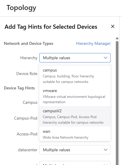
- Observe the list of existing Network Hierarchies on the left (for example: wan, datacenter, campusV2).
- The order of this list is critical. CloudVision evaluates devices from the top down. If a device's tags match the rules of Hierarchy 1, it is placed there and evaluation stops. If not, it moves to Hierarchy 2, and so on.
- You can reorder the list by clicking a hierarchy name and dragging it to the new position, prioritizing which logic applies first.
- Click campusV2 and move it to the top.
- With campusV2 highlighted, review the center panel with the campusV2 hierarchy shown.
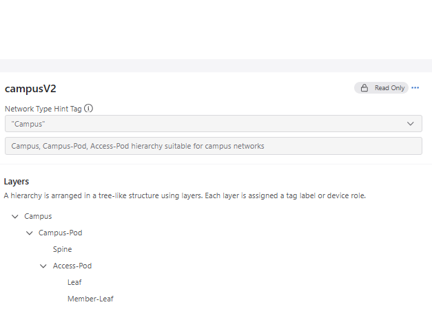
-
Note that it differs slightly from our desired topology.
-
Campus
- Campus-Pod
- Spine
- Access-Pod
- Leaf
- Member-Leaf
- Host
-
Click Done.
Lab Tasks – First look at the campusV2 Topology
-
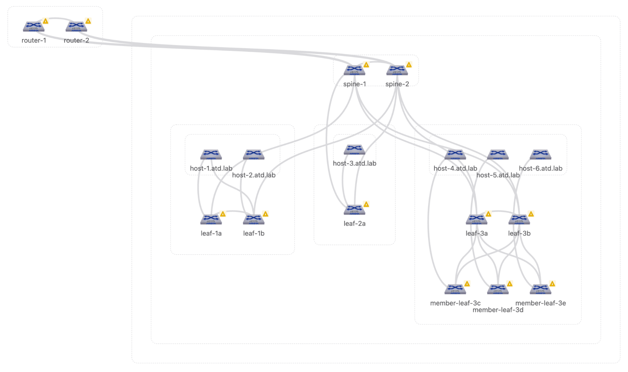
Expand the tiers and double click the icons to reveal all the switches. Note* Device Selection As we move forward, remember that device selection can be done in multiple ways.
-
Click on a rectangle to select all the devices in that rectangle.
- Click on a single device/rectangle.
- Click on one device, hold the shift key down (cross-hairs appear) and click on other devices/rectangles one at a time.
- Hold the shift key down, click and drag across one or many devices/rectangles.
- Click the lasso button, click and drag across one or many devices/rectangles.
-
Click the pointer button
 to return to normal operations.
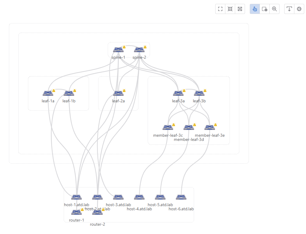
-
Click Zoom to Fit, then use the lasso tool to select all switches.
-
On the left, click Edit Tag Hints and select Hierarchy: campusV2.
-
Click Apply, then click Zoom to Fit.
-
Hover over each of the rectangular boxes and review the tags: Campus, Campus-pod, Access-pod, Spine and Untagged.
-
Later in the lab, we are going to create a custom hierarchy from the campusV2 hierarchy to accommodate our topology.
-
Click the Topology Settings Icon (gear) and then Edit.
Lab Tasks – Building the CT-Colo Campus Hierarchy
The Hierarchy Manager defines the "top-down" logic CloudVision uses to evaluate device placement on the map.
A custom hierarchy is constructed in a tree-like formation consisting of layers. Each layer is associated with a tag label or value, which can be assigned in Topology using Tags Hints.
Each layer has several inputs that associate it with a tag and configure how it is displayed.
We will create two campus hierarchies, one for CT-Colo and one for Hartford. We will start with the smaller CT-Colo site. Here are the hierarchies we documented earlier:
-
Campus
- Data-Center
- core
- Data-Center
-
Campus
- Campus-Pod
- Spine
- Access-Pod
- Leaf
- Member-Leaf
- Host
- Campus-Pod
-
Click + New at the top right of the Network Hierarchies panel.
-
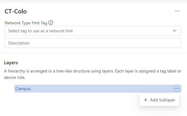
In the Name field, enter CT-Colo. Click Confirm.
-
Click CT-Colo in the Network Hierarchy list on the left.
-
You are now inside the builder for this specific hierarchy.
-
Leave the Network Type Hint Tag and Description empty.
-
Let's build our first layer. Click on the default Custom layer to highlight it and look at the Layer Properties panel on the right.
-
Configure the layer properties as follows to create the Building layer:
-
Device Role: Campus This defines the conceptual name of the layer.
-
Tag Mapping: Empty This tells CloudVision which specific Tag Label to search for under the hood to group the devices.
-
Display Name: Campus This is the text displayed on the visual container on the map. Keep the auto-fill of Campus.
-
Display Alignment: Horizontal This determines how the internal nodes are drawn within the container. The switches are placed side-by-side. (Other options: Grid, Vertical and Rack)
-
Collapsible: ON Allow the operator to expand or collapse this specific container on the main topology map.
-
Layer Icon:
 Change the Layer Icon by clicking the existing icon and select: cluster-campus . This option is only available if the Collapsible Toggle is set to ON.
-
Now we will create a sublayer. Click the ... next to the Campus layer and add a Sublayer.
-
In this new layer, set the Device Role to Data-Center.
-
In a sublayer, you can set the rules that suggest specific devices be included in this tier.
-
Leave Host Name Hint, and Host Description Hint empty for our demonstration.
-
Remaining settings:
-
Tag Mapping: Empty
-
Display Name: Data-Center
-
Display Alignment: Horizontal
-
Collapsible: ON
-
Layer Icon: Find and select cluster-datacenter
-
-
Click the ... next to the Data-Center layer and add a Sublayer.
-
Click the > next to Data-Center to reveal the sublayer.
-
Click NewLayer and configure the layer properties in the panel on the right, to create the Core layer:
-
Device Role: Core. This defines the conceptual name of the layer.
Note* Filtering Devices into Sublayers* There are multiple ways to include specific devices into the tier. You can use the Host Name/Host Description hints (any switch with "core-" in its hostname), or you can use Tag Mapping* (any switch with the tag Role: core). You may need to use a combination or none at all. We will use a Host Name Hint.
-
Host Name Hint: router- (our core switches are not named core-x, we need to identify them by name)
-
Host Description Hint: Blank
-
Tag Mapping: Empty
-
Display Name: Core This is the text displayed on the visual container on the map.
-
Display Alignment: Horizontal This determines how the internal nodes are drawn within the container. The routers are placed side-by-side. (Other options: Grid, Vertical and Rack)
-
Collapsible: OFF Allow the operator to expand or collapse this specific container on the main topology map.
-
-
Click Save in the top right corner of the page to save your changes.
-
Click on the Campus parent layer and review the right panel Layer Properties.
Note:* When a parent layer gets a sublayer, the parent Layer/ Properties change.* You will see the following input option changes:
Modified
Device Role => Tag Label: Tag Label is the Name used as the Label, in a Label: Value pair.
Removed
Host Name Hint Host Description Hint
Added
Aggregate siblings with the same tag: A toggle to create a container for all children of this layer with the same tag value. Sibling Display Alignment: Determines how this layer's container in the topology display will align with its sibling layers
Lab Tasks – Modifying the campusV2 Hierarchy
We will modify the campusV2 Hierarchy to create the topology that we desire. We could create this hierarchy from scratch just as we did with CT-Colo or we could edit an existing hierarchy to make it fit our requirements, which is what we will do in this lab.
-
Click on campusV2 then click the ellipses … on the right and select duplicate.
-
In the Name field, enter Hartford. Click Duplicate.
-
Click Hartford in the Network Hierarchy list on the left.
-
You are now inside the builder for this specific hierarchy.
-
In the center panel near the top, you will see the Network Type Hint Tag. Click the dropdown menu. You will notice that you select a Tag Label here; this dictates the highest-level groupings on your topology map. For our CT-Colo hierarchy, leave this blank, as we are defining the root container manually.
-
Here is the topology we documented earlier:
-
Campus
- Campus-Pod
- Spine
- Access-Pod
- Leaf
- Member-Leaf
- Host
- Campus-Pod
-
Click the > next to Access-Pod to expand the layer.
-
Click the ellipses … on the right of the Access-Pod layer and select +Add Sublayer. For the NewLayer create the Host layer with the following properties:
-
Device Role: Host
-
Host Name Hint: host
-
Host Description Hint: host
-
Tag Mapping: Empty
-
Display Name: Host
-
Display Alignment: Horizontal
-
Collapsible: ON
-
Layer Icon: Find and select the generic

-
Click Save and then Done.

Lab Tasks – Tag Assignments
Note: Device Selection. As we move forward, remember that device selection can be done in multiple ways:
- Click on a rectangle to select all the devices in that rectangle
- Click on a single device/rectangle
- Click on one device, hold the shift key down (cross-hairs appear) and click on other devices/rectangles one at a time.
- Hold the shift key down, click and drag across one or many devices/rectangles.
- Click the lasso button, click and drag across one or many devices/rectangles.
- Click the pointer button
 to return to normal operations
- Click Zoom to Fit.
- Double-click the icons until all of the switches are shown.
- Find and select router-1 and router-2.
- If necessary, click Edit Tag Hints.
-
In the left Panel make these selections or create the following:
- Hierarchy: CT-Colo
- Device Role: Core
- Campus: Type Colo then click + Create “Colo”
- Data-Center: Type 01-Colo then click + Create “01-Colo”
- Click Apply.
-
Select all the remaining switches (not router-1, router-2)
- In the left Panel make these selections
- Hierarchy: Hartford
- Device Role: Multiple values
- Campus: Hartford
- Campus-Pod: East-Campus
- Access-Pod: Multiple values
- Click Apply.
-
Click Zoom to Fit and double click to expand all containers if necessary, then find and select spine-1and spine-2
- Hierarchy: Hartford
- Device Role: Spine
- Campus: Hartford
- Campus-Pod: East-Campus
- Access-Pod: None
- Click Apply
-
Expand all the containers
-
Select leaf-1a and leaf-1b
-
Click Edit Tag Hints
-
Confirm, Select or Create the following entries
- Hierarchy: Hartford
- Device Role: Leaf
- Campus: Hartford
- Campus-Pod: East-Campus
- Access-Pod: Bldg10
- Click Apply
-
Select leaf-2a
- Hierarchy: Hartford
- Device Role: Leaf
- Campus: Hartford
- Campus-Pod: East-Campus
- Access-Pod: Bldg20
- Click Apply
-
Select leaf-3a and leaf-3b
- Hierarchy: Hartford
- Device Role: Leaf
- Campus: Hartford
- Campus-Pod: East-Campus
- Access-Pod: Bldg30
- Click Apply
-
Select member-leaf-3c, member-leaf3d, and member-leaf-3e
- Hierarchy: Hartford
- Device Role: Member-Leaf
- Campus: Hartford
- Campus-Pod: East-Campus
- Access-Pod: Bldg30
- Click Apply
-
Select host-1.atd.lab and host-2.atd.lab
- Hierarchy: Hartford
- Device Role: Host
- Campus: Hartford
- Campus-Pod: East-Campus
- Access-Pod: Bldg10
- Click Apply
-
Select host-3.atd.lab
- Hierarchy: Hartford
- Device Role: Host
- Campus: Hartford
- Campus-Pod: East-Campus
- Access-Pod: Bldg20
- Click Apply
-
Select host-4.atd.lab, host-5.atd.lab, and host-5.atd.lab
- Hierarchy: Hartford
- Device Role: Host
- Campus: Hartford
- Campus-Pod: East-Campus
- Access-Pod: Bldg30
- Click Apply
-
Click the outer-most boxes and note the descriptions - Campus: Colo & Campus: Hartford.
-
Click each of the boxes to confirm proper assignments.
Campus
- Data-Center
- Core
Campus
- Campus-Pod
- Spine
- Access-Pod
- Leaf
- Member-Leaf
- Host
If your topology looks like this, you’re done. Congratulations.