Lab 8: External Devices
We move beyond our internal fabric to establish connectivity with the Outside World—typically your Core or WAN routers.
Lab Tasks – Modify Router1 and Router2 running configurations
We’ve built a great internal network, but now it’s time to give it an exit strategy. We’re heading to the CLI of router-1 and router-2 to manually prep them for Layer 3 connectivity. We’re setting up point-to-point links, loopbacks for management, and static routes so these routers know how to get back into our campus fabric. This is a classic 'Border' configuration where the automation of CloudVision meets the traditional CLI of the Core.
-
Navigate to the Arista Campus Lab in your browser
ROUTER 1
-
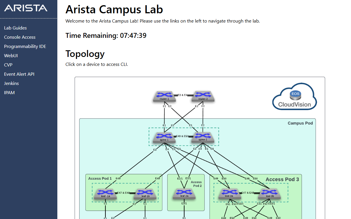
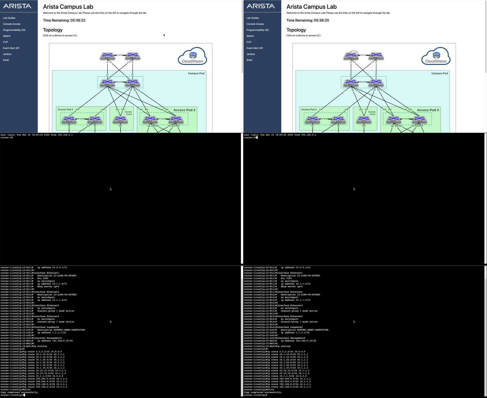
Locate router-1 in the Topology diagram and click the icon to access the CLI.
-
Paste the following configuration at the switch console.
Config
interface Port-Channel1
   description L3-INTER-CORE-LINK
   no switchport
   ip address 10.0.0.1/31
!
interface Ethernet1
   description L3-LINK-TO-SPINE1
   mtu 1500
   no switchport
   ip address 10.1.1.0/31
   dhcp server ipv4
!
interface Ethernet2
   description L3-LINK-TO-SPINE2
   no switchport
   ip address 10.1.1.2/31
!
interface Ethernet3
   no switchport
   channel-group 1 mode active
!
interface Ethernet4
   no switchport
   channel-group 1 mode active
!
interface Loopback0
   description ROUTER1-MGMT-IDENTIFIER
   ip address 1.1.1.1/32
!
interface Management0
   ip address 192.168.0.10/24
!
ip routing
!
ip route 2.2.2.2/32 10.0.0.0
ip route 10.1.10.0/24 10.1.1.1
ip route 10.1.10.0/24 10.1.1.3
ip route 10.1.20.0/24 10.1.1.1
ip route 10.1.20.0/24 10.1.1.3
ip route 10.1.30.0/24 10.1.1.1
ip route 10.1.30.0/24 10.1.1.3
ip route 10.10.10.0/24 10.1.1.1
ip route 10.10.10.0/24 10.1.1.3
ip route 10.1.1.0/24 10.0.0.0
ip route 169.254.0.0/24 10.1.1.1
ip route 169.254.0.0/24 10.1.1.3
ip route 192.168.0.0/24 10.1.1.1
ip route 192.168.0.0/24 10.1.1.3
Write
ROUTER 2
-
Locate router2 in the Topology diagram and click the icon to access the CLI.
-
Paste the following configuration at the switch console.
Config
interface Port-Channel1
   description L3-INTER-CORE-LINK
   no switchport
   ip address 10.0.0.0/31
!
interface Ethernet1
   description L3-LINK-TO-SPINE1
   no switchport
   ip address 10.1.1.4/31
!
interface Ethernet2
   description L3-LINK-TO-SPINE2
   no switchport
   ip address 10.1.1.6/31
!
interface Ethernet3
   no switchport
   channel-group 1 mode active
!
interface Ethernet4
   no switchport
   channel-group 1 mode active
!
interface Loopback0
   description ROUTER2-MGMT-IDENTIFIER
   ip address 2.2.2.2/32
!
ip routing
!
ip route 1.1.1.1/32 10.0.0.1
ip route 10.1.10.0/24 10.1.1.5
ip route 10.1.10.0/24 10.1.1.7
ip route 10.1.20.0/24 10.1.1.5
ip route 10.1.20.0/24 10.1.1.7
ip route 10.1.30.0/24 10.1.1.5
ip route 10.1.30.0/24 10.1.1.7
ip route 10.10.10.0/24 10.1.1.5
ip route 10.10.10.0/24 10.1.1.7
ip route 10.1.1.0/24 10.0.0.1
ip route 169.254.0.0/24 10.1.1.5
ip route 169.254.0.0/24 10.1.1.7
ip route 192.168.0.0/24 10.1.1.5
ip route 192.168.0.0/24 10.1.1.7
write
Lab Tasks – Reconcile Router configurations
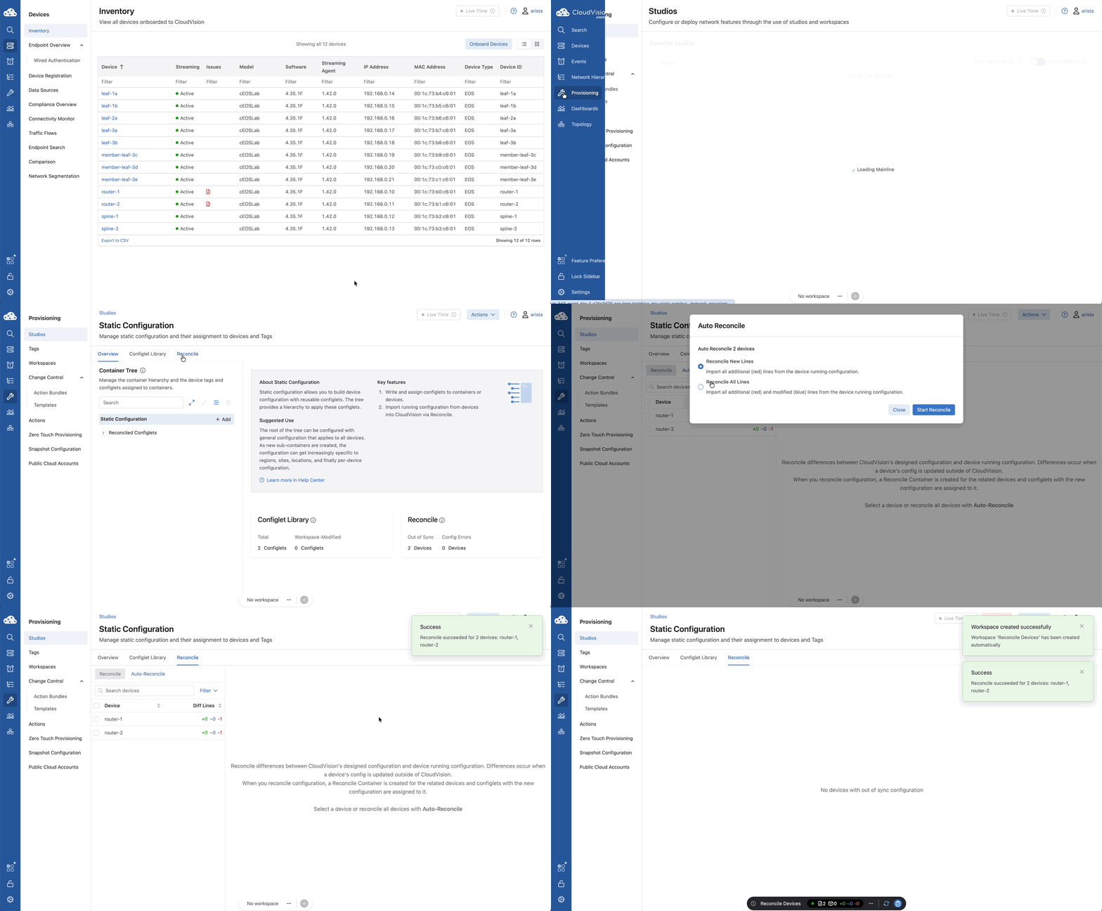
You’ll see the familiar red icons in CloudVision. Since we want to keep those manual configurations, we’re using Auto-Reconcile.
We are telling CloudVision: 'I did some manual work on the core routers, please import those lines and make them the new Source of Truth'.
This ensures our core routers stay 'In Compliance' even though they were configured outside of a Studio.
-
Navigate back to CloudVision
-
Select Provisioning > Studios > Static Configuration Studio
-
Click Reconcile, then Select Auto-Reconcile
-
Click Reconcile All Lines then Click Start Reconcile
Lab Tasks – External Core Routers
Now we return to the Campus Fabric Studio to define our Egress Connectivity.
We're adding router1 and router2 as External Devices.
Even though CloudVision isn't pushing a full config to these routers, it needs to know their IP addresses and interface names.
Why? Because once CloudVision knows that spine-1 is connected to router1 at 10.1.1.0/31, it can automatically build the correct IP and MTU settings on the spine's Ethernet interface.
We’re also forcing the speed to 1gfull to ensure there’s no negotiation guesswork between different hardware generations.
-
Navigate to Provisioning > Studios > Campus Fabric Studio
-
Select Campus Fabric Hartford > then Campus Pod Bldg1 >
-
Scroll down to Egress Connectivity in the left panel, and Click External Devices
-
Click Add External Device and enter:
- Device Name: router1
- Device Name: router2
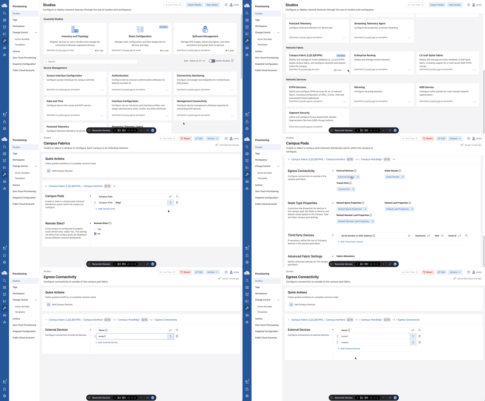
CloudVision is not managing Router1 and Router2. The Studio needs to know they exist and some details so it can build the connection.
-
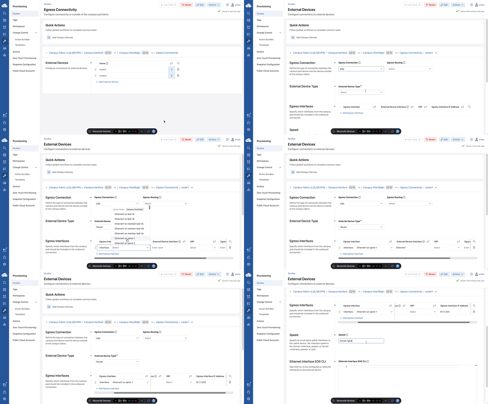
Click router1
-
Set Egress Connection: to p2p and External Device Type: to router
-
Enter the following details for Router1
External Device Egress Interface External Device Interface VRF Egress Interface IP Address router1 Ethernet 1 on spine-1 Ethernet1 - 10.1.1.1/31 router1 Ethernet 1 on spine-2 Ethernet2 - 10.1.1.3/31 -
Set Speed to auto
-
Use down arrow next to router1 (in the fabric hierarchy line) to switch to router2
-
Set Egress Connection: to p2p and External Device Type: to router
-
Enter the following details for router2
External Device Egress Interface External Device Interface VRF Egress Interface IP Address router2 Ethernet 2 on spine-1 Ethernet1 - 10.1.1.5/31 router2 Ethernet 2 on spine-2 Ethernet2 - 10.1.1.7/31 -
Set Speed to auto
Lab Tasks – Default Routes
We are adding four static routes—two for each spine—pointing to both core routers.
Because we have multiple paths with equal costs, the Arista EOS operating system will automatically perform ECMP.
This means your egress traffic is balanced across both routers, giving you double the bandwidth and instant failover if a core link goes dark.
-
Return to the Campus-Pod:Bldg1 page (by clicking Campus-Pod:Bldg1)
-
Navigate to Egress Connectivity, and click Static Routes.
-
Click + Add Static Route
- spine-1 to router1
- spine-1 to router2
- spine-2 to router1
- spine-2 to router2
-
Click spine-1 to router1
-
Click + Add Device click device:spine1
-
Destination Address Prefix: 0.0.0.0/0
-
Gateway: 10.1.1.0
-
Add the other default routes according to the table below.
| Link Description | Tag Query | Destination Address Prefix | Gateway |
|---|---|---|---|
| spine-1 to router2 | device: spine-1 | 0.0.0.0/0 | 10.1.1.4 |
| spine-2 to router1 | device: spine-2 | 0.0.0.0/0 | 10.1.1.2 |
| spine-2 to router2 | device: spine-2 | 0.0.0.0/0 | 10.1.1.6 |
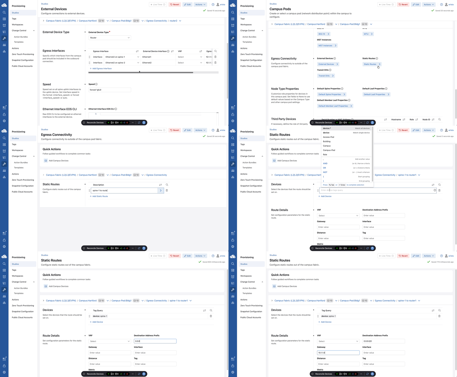
Lab Tasks – Change Control Review and Submission
-
Click the review and submit on the Workspace Island
-
Review the configurations, then click Submit Workspace
-
Click View Change Control, then Review and Approve, and finally Approve and Execute.
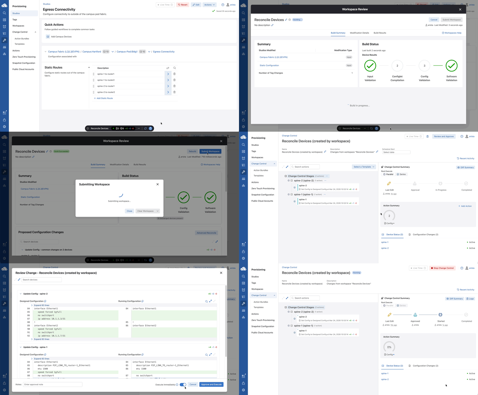
You could also use the Static Configuration Studio to add the default routes.
Configlet for spine-1: “spine-1 default routes”
ip route 0.0.0.0/0 10.1.1.0 name spine-1_to_router1
ip route 0.0.0.0/0 10.1.1.4 name spine-1_to_router2
Configlet for spine-2: “spine-2 default routes”
ip route 0.0.0.0/0 10.1.1.2 name spine-2_to_router1
ip route 0.0.0.0/0 10.1.1.6 name spine-2_to_router2
Lab Tasks – Validation
After we submit our workspace and clear the Change Control, it’s time for the moment of truth.
We’ll jump onto the Spine CLIs and try to ping the loopback addresses (1.1.1.1 and 2.2.2.2) on the core routers.
If those pings return successfully, it means your automated campus fabric is now talking to your manual core.
-
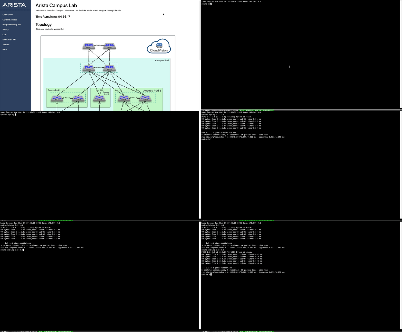
From Spine-1 and Spine-2 Ping 1.1.1.1 on router1
-
From Spine-1 and Spine-2 Ping 2.2.2.2 on router2