Lab 7 - Network Hierarchy
The Network Hierarchy provides a centralized view to monitor and manage your campus. From this view, you can quickly drill down from an aggregated global state to individual interfaces to view device and port details.
In this lab, you will also apply Interface Profiles (created in a previous lab) directly to ports via the Front Panel view.
Lab Tasks – The Campus Hierarchy (left panel)
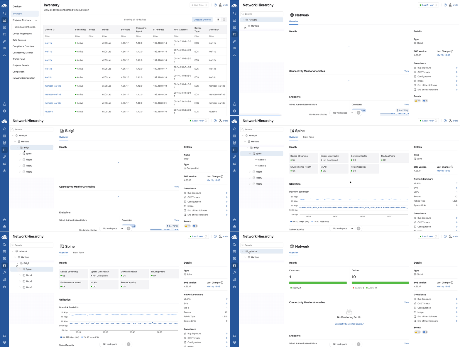
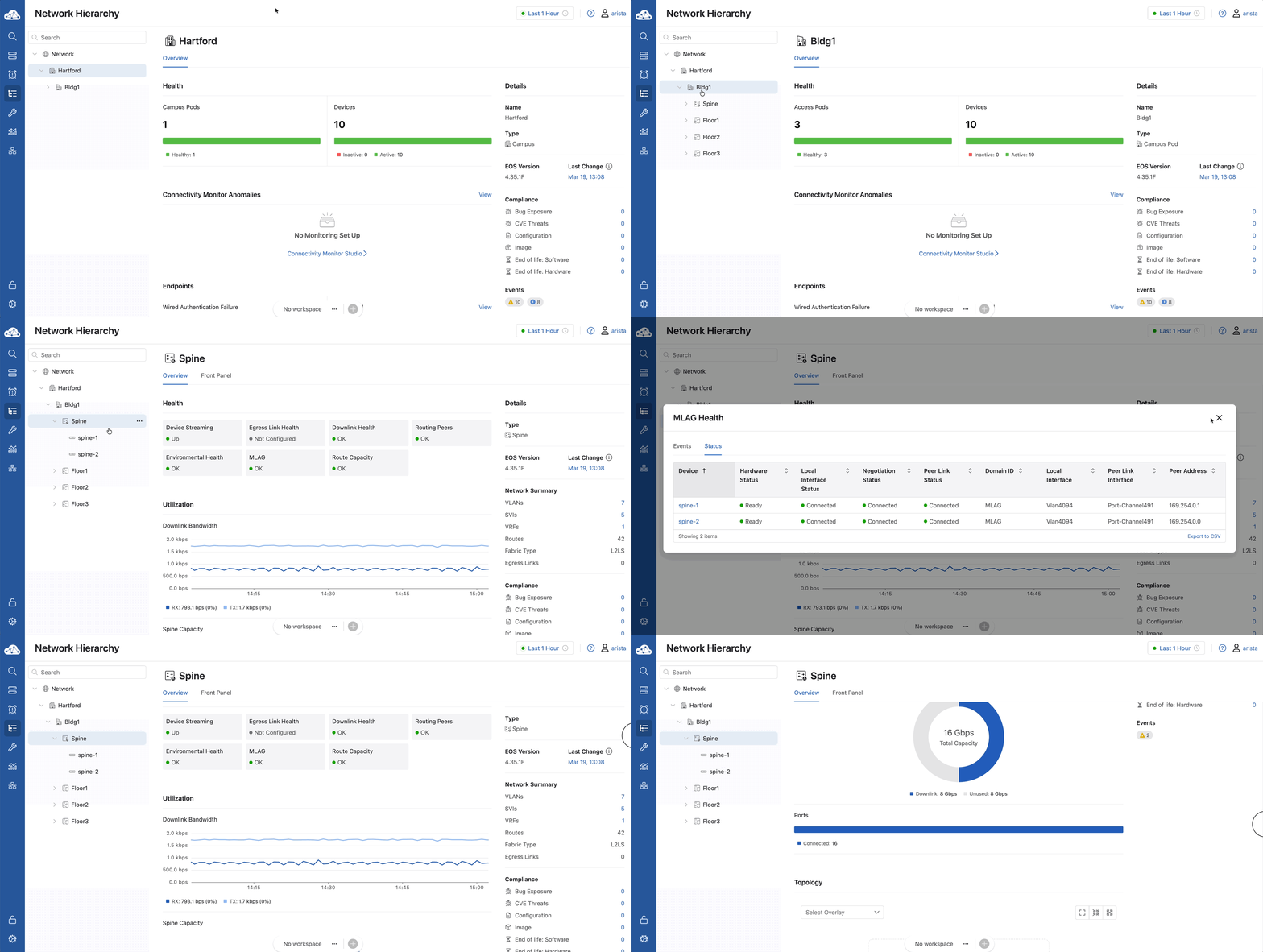
By selecting Network Hierarchy, you’re looking at a live, logical map of your entire Hartford campus. As you expand the tiers, you’ll see the structure we built earlier: Bldg1 as the pod, followed by your Spines and individual **Floorsv. This isn't just a static list; it’s a real-time health dashboard. If a link goes down on Floor 3, the 'Hartford' top-level icon will reflect that change immediately.
- Hover over the blue selection panel on the left and select Network Hierarchy.
- Expand all tiers of the hierarchy by clicking the > next to each name.
- Note: This reflects the topology built earlier in the Campus Fabric studio.
Note
If you navigate deep into a sub-page, use your browser's back arrow to return to the main Network Hierarchy view.
Lab Tasks – Hartford (The Campus Fabric)
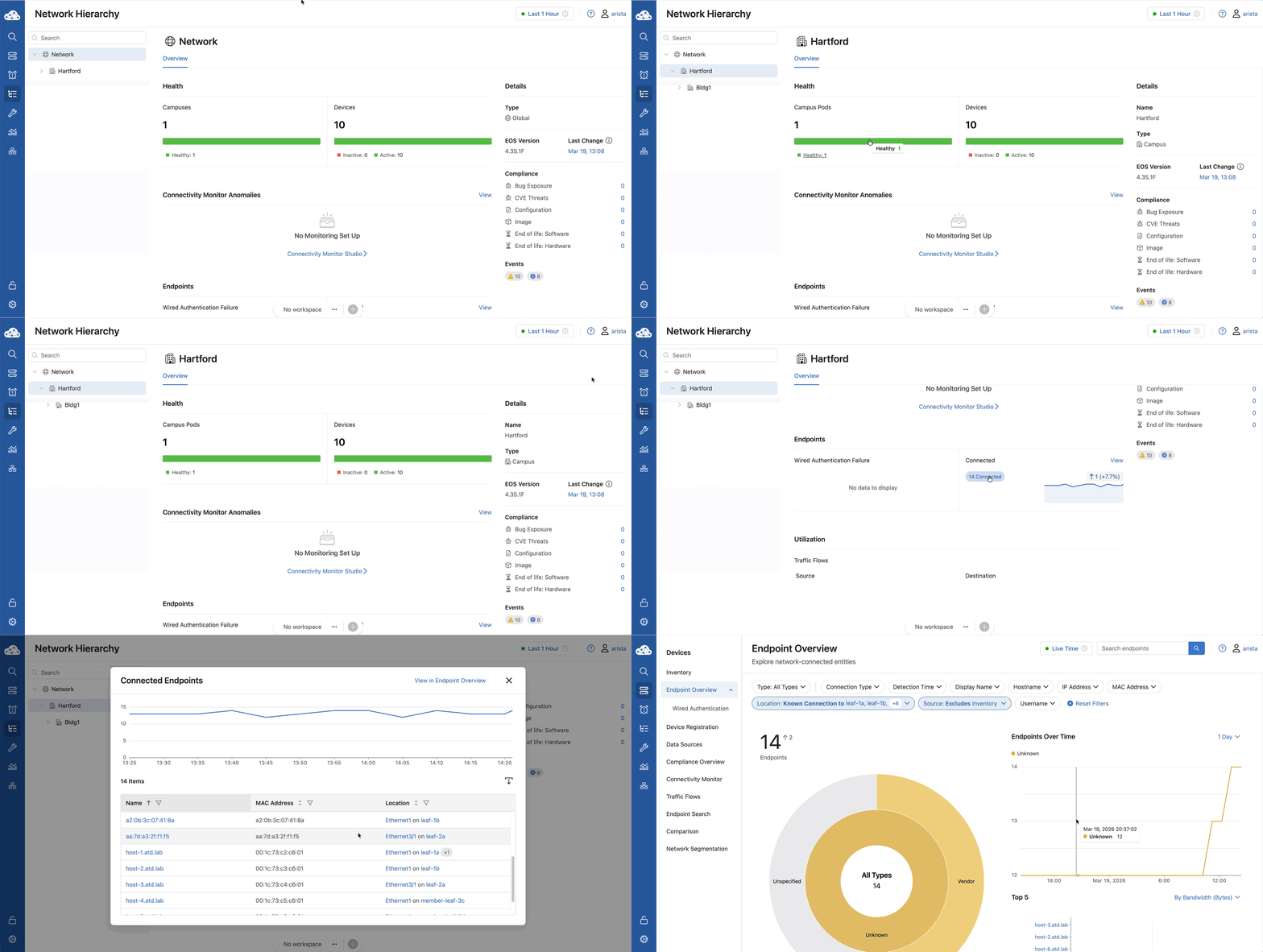
- Click Hartford at the top of the hierarchy. The metrics will update to reflect the entire campus.
- Health: Click the green line in the Campus Pods and Devices sections respectively. This quickly shows health status details.
- Endpoints: Click the ## Connected button to see the Connected Endpoints list. (Clicking blue names/locations will show deeper details).
- Endpoints: Click View to display the Endpoint Overview page.
-
Return the Network Hierarchy page by using your browser's back button.
-
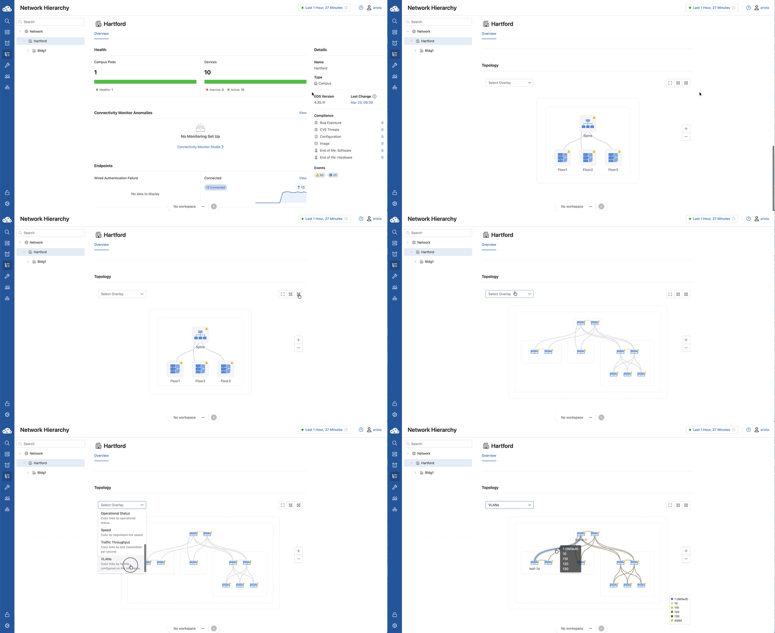
Scroll down to the Topology panel and expand it. We’re going to change our view by selecting the VLANs Overlay. Now, when you hover over the links, you aren't just seeing 'connected' or 'disconnected'; you’re seeing exactly which VLANs are permitted to travel across those wires.
-
Topology: Scroll Down to find the Topology panel near the bottom of the Network Hierarchy and click the Expand icon(the third icon on the right: a square with arrows).
- Click the Select Overlay dropdown and select VLANs.
- Hover over the links in the diagram to see assigned VLANs.
-
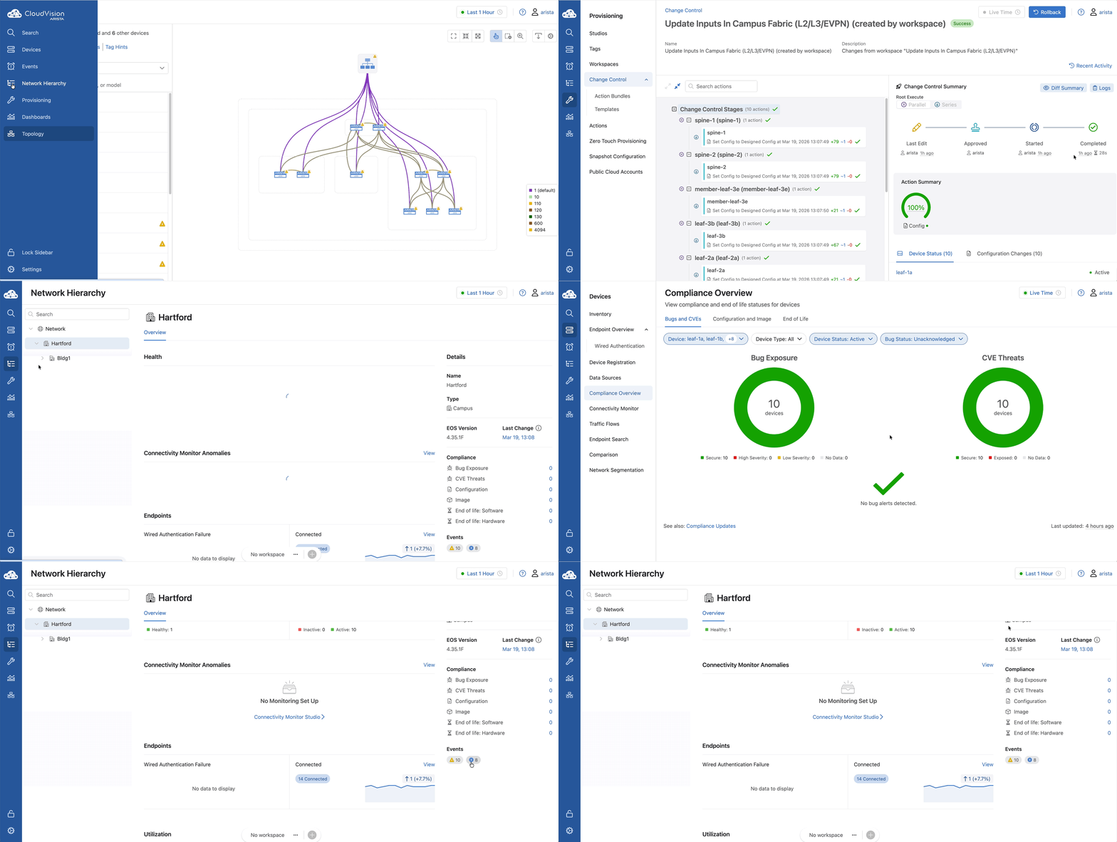
Scroll to the top-right panel - Details
- Click the date under Last Change to view the latest change submitted for these devices.
- In the Compliance section, click the blue numbers to open the Compliance Overview.
- Under Events (bottom of the panel), click the event buttons to see specific network alerts.
Lab Tasks – Bldg1 (Campus Pod)
- Click Bldg1 in the Network Hierarchy.
- Observe that the information is now filtered specifically for devices under the Bldg1 Campus-Pod.
Lab Tasks – Spine (Spine-1, 2)
- Click Spine in the hierarchy and stay on the Overview tab.
- Health: Click the MLAG boxes for additional info.
- Exploration: Review the Utilization, Spine Capacity, Ports, and the Details panel on the right.
Lab Tasks – Floor1, Floor2, Floor3 (Access Pods)
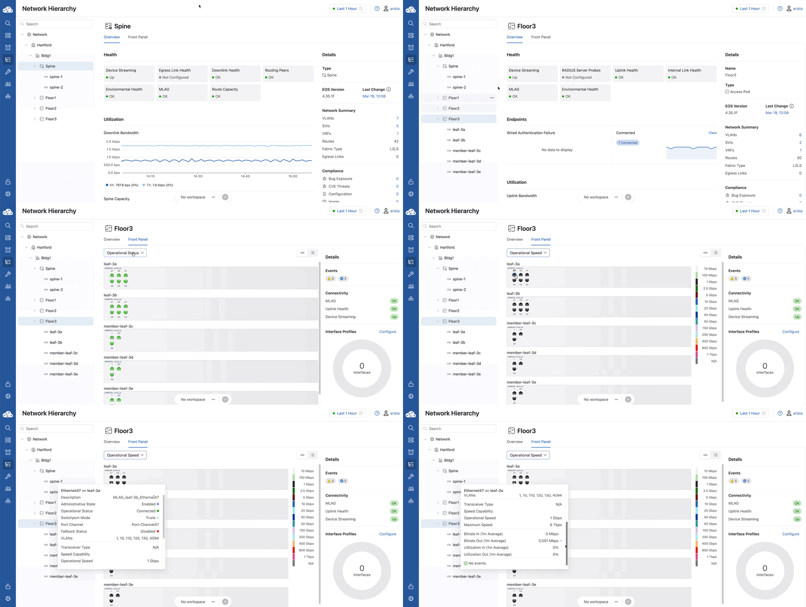
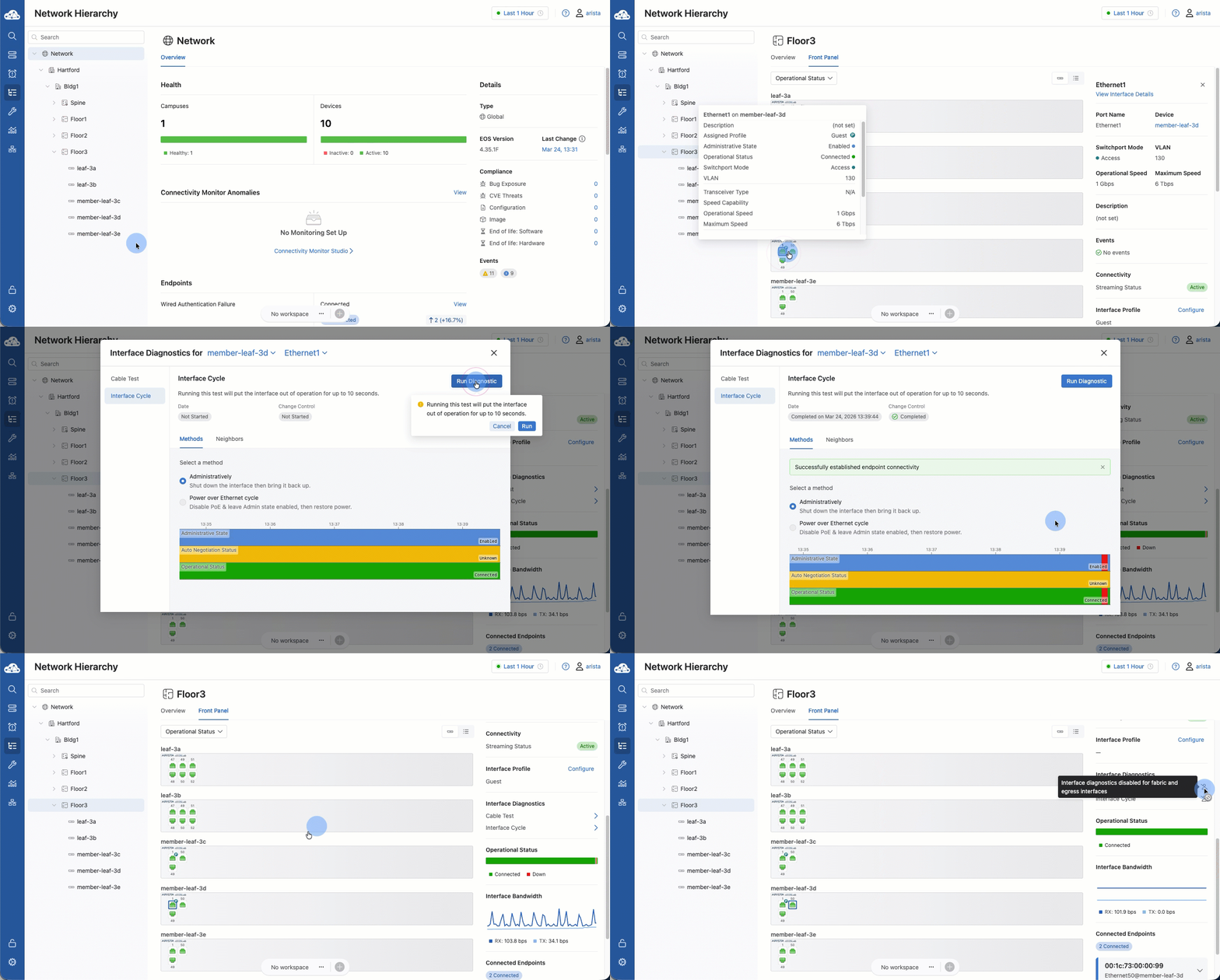
We’re going to Floor 3 and opening the Front Panel view. This looks exactly like the physical switch sitting in the wiring closet. Remember those Port Profiles (CORP and GUEST) we built earlier?
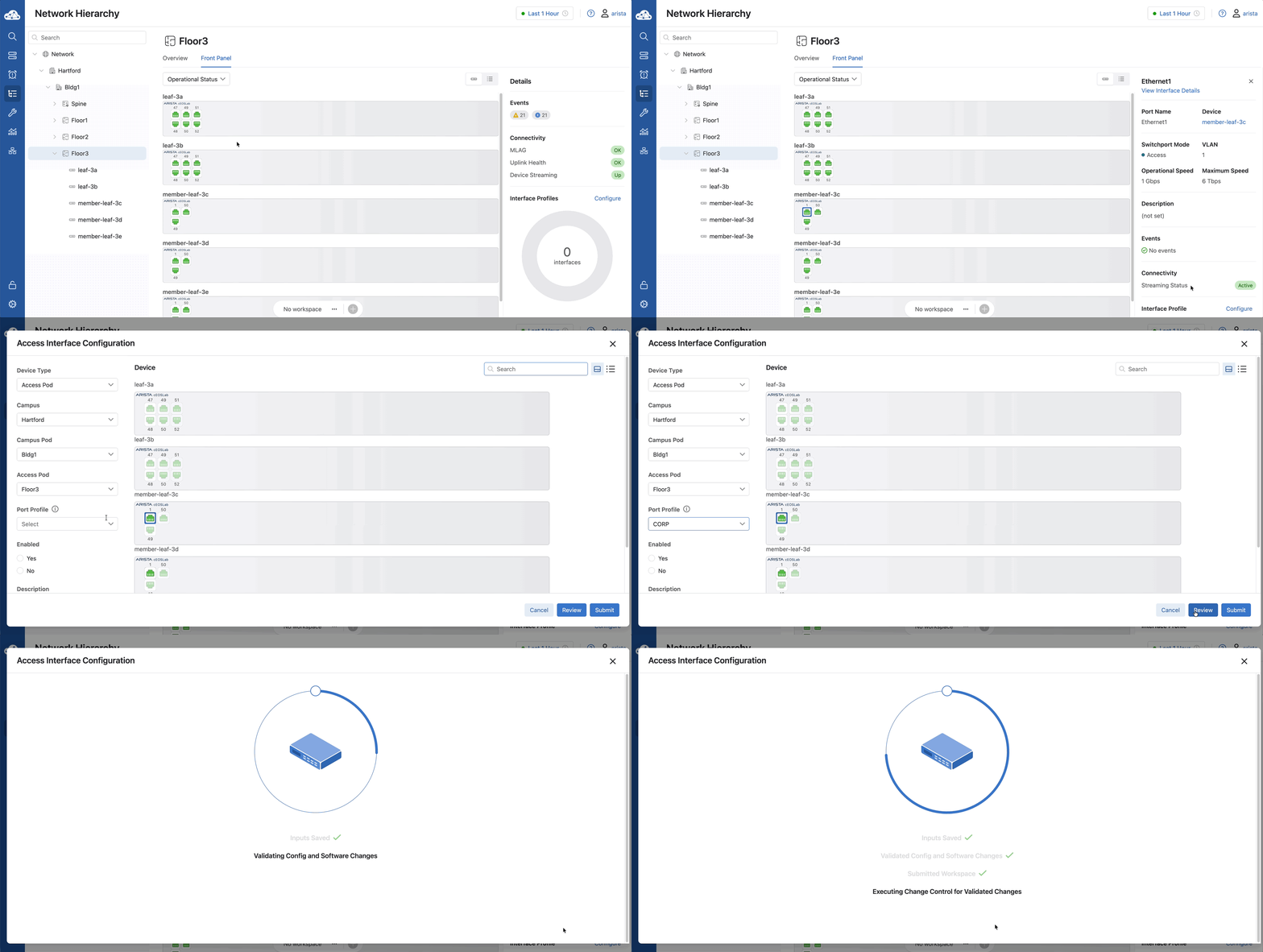
When we select Ethernet1 and assign the CORP profile, we are pushing that entire block of configuration—VLANs, phone settings, and descriptions—in one click. Notice that some buttons offer a 'Review' while others just say 'Submit'. 'Submit' executes the change immediately.
- Click Floor3 in the Network Hierarchy.
- Select the Front Panel tab.
- Click the drop-down box to change overlays (Operational/Maximum Speed) to see color-coded port gradients.
-
Hover over the ports to view the current status and diagnostic data.
-
In the right panel, find Interface Profile and click Configure.
- Click member-leaf-3c Ethernet1.
- On the Access Interface Configuration page, find the Port Profile box (left side) and select CORP.
- Click Review, then click Confirm.
-
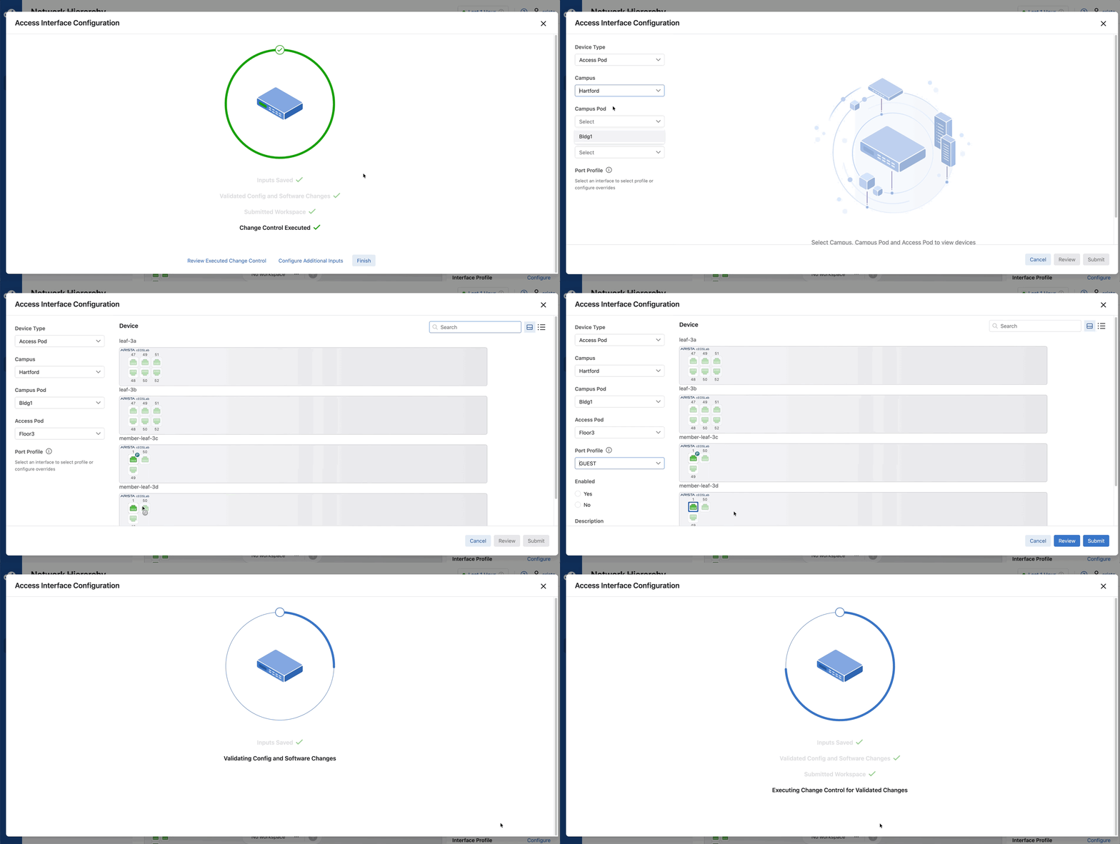
Click Finish
-
Select member-leaf-3d Ethernet1
- In the right panel, find Interface Profile and click Configure.
- In the Port Profile box, select GUEST
- Click Submit
- Notice by clicking Submit the change is executed immediately with no review.
-
Click Finish
-
A “P” icon now exists near member-leaf-3c Port 1, and member-leaf-3d Port 1 indicating a Profile is assigned.
- Hover over the port to verify the assignment.
Lab Tasks – Troubleshooting
- Click Floor3 in the Network Hierarchy.
- Click the Front Panel view
- Select Ethernet1 on either of the two switches that have a port profile assigned
- On the right panel, click Interface Cycle
- Click Run Diagnostic, then Run
- This is an easy way to “bounce” a port without having to log into CLI
- Close out of this window and select Ethernet50
- Hover over Cable Test & Interface Cycle
- Notice how CloudVision does not allow you to run this test on a fabric link, preventing inadvertent outages on your network.
Lab Tasks – Confirmation
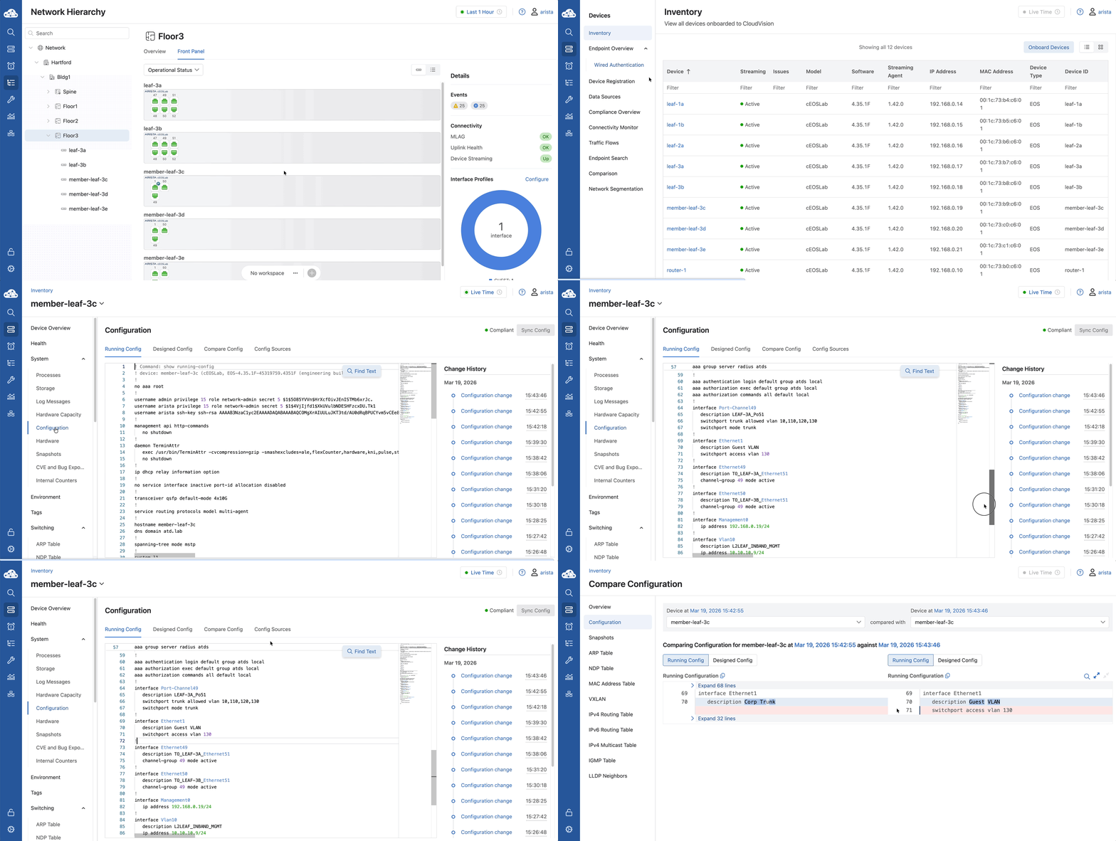
We’re going back to the Inventory to look at the Running Config of member-leaf-3c. Search for Ethernet1, and you'll see the exact commands from our CORP profile sitting in the config.
Check the Change History—you’ll see the exact 'Before and After' of your change. Congratulations, you've completed the lab series!
- Navigate to Devices > Inventory and click member-leaf-3c.
- Click Configuration in the left-hand panel.
- Click Running Config and Scroll down to see the interface Ethernet1 configuration.
- In the Change History section (right side), click the most recent Configuration change.
- Verify the Running Config before and after the change.
You have completed the lab!