Lab 6 - Campus Fabric Studios - External Device
We bridge the gap between our automated campus fabric and the external core network using dynamic routing (OSPF) and high-availability peering (MLAG).
Lab Tasks – Modify Router1 and Router2 running configurations
We’re moving beyond the internal fabric to connect to our core routers. We’ll start by jumping into the CLI of router-1 and router-2. We’re applying a configuration that includes an MLAG peer-link between the two routers and OSPF to handle the routing.
These external devices could be firewalls, a provider or legacy routers. In our virtual lab, CVaaS is monitoring those routers but we haven’t yet integrated them into our fabric.
This is a 'manual handshake'—we are preparing the external world to talk to our automated CloudVision environment.
1) Navigate to the Arista Campus Lab in your browser
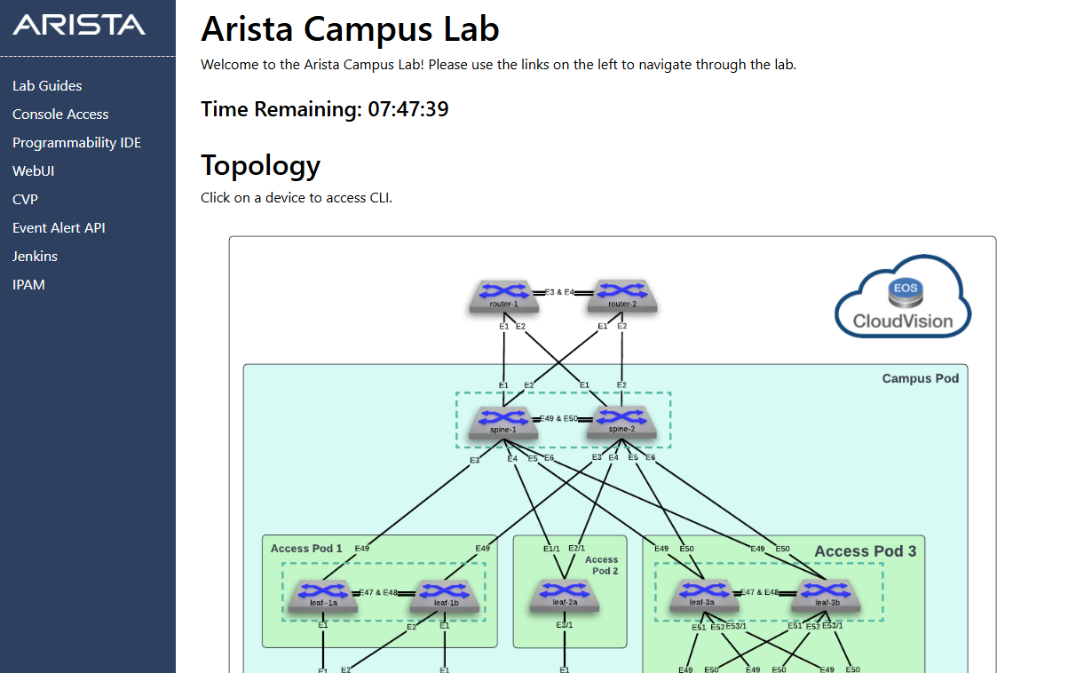
2) Locate router-1 in the Topology diagram and click the icon to access the CLI. 3) Paste the following configuration at the switch console.
Config
\!
no spanning-tree vlan-id 4094
\!
vlan 4094
   name MLAG\_PEER
   trunk group MLAG
\!
interface Port-Channel3
   description MLAG\_PEER\_router-2\_Po3
   switchport mode trunk
   switchport trunk group MLAG
   switchport
\!
interface Ethernet1
   description L3-LINK-TO-SPINE1
   no switchport
   ip address 10.1.1.0/31
  ip ospf network point-to-point
  ip ospf area 0.0.0.0
\!
interface Ethernet2
   description L3-LINK-TO-SPINE2
   no switchport
   ip address 10.1.1.2/31
  ip ospf network point-to-point
   ip ospf area 0.0.0.0
\!
interface Ethernet3
   description MLAG\_router-2\_Ethernet3
   no switchport
   channel-group 3 mode active
\!
interface Ethernet4
   description MLAG\_router-2\_Ethernet4
   no switchport
   channel-group 3 mode active
\!
interface Loopback0
   description ROUTER\_ID
   ip address 172.16.0.11/32
   ip ospf area 0.0.0.0
\!
Interface loopback1
  Description VALIDATION\_IP\_ADDRESS
 Ip address 1.1.1.1/32
Ip ospf area 0.0.0.0
\!
interface Vlan4094
   description MLAG\_PEER
   mtu 1500
   no autostate
   ip address 169.254.0.0/31
   ip ospf network point-to-point
   ip ospf area 0.0.0.0
\!
ip routing
\!
mlag configuration
   domain-id MLAG
   local-interface Vlan4094
   peer-address 169.254.0.1
   peer-link Port-Channel3
   reload-delay mlag 300
   reload-delay non-mlag 330
\!
router ospf 100
   router-id 172.16.0.11
   passive-interface default
   no passive-interface Vlan4094
   no passive-interface Ethernet1
   no passive-interface Ethernet2
   no passive-interface Ethernet3
   no passive-interface Ethernet4
   redistribute connected
  redistribute static
   max-lsa 12000
\!
End
\!
Write
1) Locate router-2 in the Topology diagram and click the icon to access the CLI. 2) Paste the following configuration at the switch console.
Config
\!
no spanning-tree vlan-id 4094
\!
vlan 4094
   name MLAG\_PEER
   trunk group MLAG
\!
interface Port-Channel3
   description MLAG\_PEER\_router-1\_Po3
   switchport mode trunk
   switchport trunk group MLAG
   switchport
\!
interface Ethernet1
   description L3-LINK-TO-SPINE1
   no switchport
   ip address 10.1.1.4/31
   ip ospf network point-to-point
   ip ospf area 0.0.0.0

\!
interface Ethernet2
   description L3-LINK-TO-SPINE2
   no switchport
   ip address 10.1.1.6/31
   ip ospf network point-to-point
   ip ospf area 0.0.0.0

\!
interface Ethernet3
   description MLAG\_router-1\_Ethernet3
   no switchport
   channel-group 3 mode active
\!
interface Ethernet4
   description MLAG\_router-1\_Ethernet4
   no switchport
   channel-group 3 mode active
\!
interface Loopback0
   description ROUTER\_ID
   ip address 172.16.0.12/32
   ip ospf area 0.0.0.0
\!
Interface loopback1
  Description VALIDATION\_IP\_ADDRESS
 Ip address 2.2.2.2/32
Ip ospf area 0.0.0.0
\!
interface Vlan4094
   description MLAG\_PEER
   mtu 1500
   no autostate
   ip address 169.254.0.1/31
   ip ospf network point-to-point
   ip ospf area 0.0.0.0
\!
ip routing
\!
mlag configuration
   domain-id MLAG
   local-interface Vlan4094
   peer-address 169.254.0.0
   peer-link Port-Channel3
   reload-delay mlag 300
   reload-delay non-mlag 330
\!
ip route 0.0.0.0/0 Null0
\!
router ospf 100
   router-id 172.16.0.12
   passive-interface default
   no passive-interface Ethernet1
   no passive-interface Ethernet2
   no passive-interface Ethernet3
   no passive-interface Ethernet4
   no passive-interface Vlan4094
   redistribute connected
  redistribute static
   max-lsa 12000

\!
Write
Lab Tasks – Reconcile Router configurations
Once you've pasted those configurations, CloudVision will flag the routers with red icons. It sees that the reality on the switches has changed.
Since these routers are our 'External Core', we don't want CloudVision to overwrite our work. We’ll use Auto-Reconcile in the Static Configuration Studio. This tells CloudVision: 'I’ve manually tuned these core routers; please accept these changes as the new source of truth'.
1) Return to CloudVision.
2) From the blue panel, select Devices > Inventory.
3) Notice how router-1 and router-2 show red icons.
4) This informs us that the running config has been changed and does not match our designed config.
5) We want to accept the changes that were made from the CLI so we will do a Config Reconcile and not a Config Sync.
6) Select Provisioning > Studios > Static Configuration Studio.
7) Click Reconcile, then click on router-1.
8) We could Reconcile one device at a time and approve one line at a time by clicking the  in the configuration display to either include or exclude the configuration line.
9) Instead lets de-select router-1 and click Auto-Reconcile.
10) In the display box see that 2 devices are available to be reconciled.
11) Click Reconcile All Lines then Click Start Reconcile.
12) A workspace is created.
in the configuration display to either include or exclude the configuration line.
9) Instead lets de-select router-1 and click Auto-Reconcile.
10) In the display box see that 2 devices are available to be reconciled.
11) Click Reconcile All Lines then Click Start Reconcile.
12) A workspace is created.
Lab Tasks – Change Control Review and Submission
1) On the Workspace Island, click Review and Submit. 2) Verify all validation checks pass and confirm the config change on all 10 devices. 3) Click Submit Workspace, then Exit Workspace.
Lab Tasks – External Core Routers
CloudVision is monitoring but not managing Router1 and Router2. The Campus Fabric Studio needs to know they exist and some details so it can build the connection.
Return to the Campus Fabric Studio to finalize the routing between the Spines and the Core. We’ll add router1 and router2 as External Devices.
By defining the Egress Interfaces and setting the routing to OSPF, we are giving the Studio the information it needs to build the 'other side' of the tunnel on our Spines. This creates a seamless, automated Layer 3 link from the heart of our campus to the core.
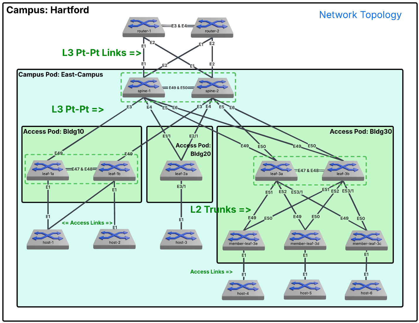
1) Navigate to Provisioning > Studios > Campus Fabric Studio. 2) Select Campus Fabric Hartford > then Campus Pod East-Campus >. 3) Scroll down to Egress Connectivity in the left panel, and Click External Devices. 4) Click Add External Device and enter: 1) Device Name: router1 2) Device Name: router2
1) Click router1. 2) Set Egress Connection: to p2p and Egress Routing: to OSPF. 3) External Device Type: to Router. 4) Enter the following details for Router1 by clicking + Add Egress Interface:
| Egress Interface | External Device Interface | VRF | Egress Interface IP Address |
|---|---|---|---|
| Ethernet 1 on spine-1 | Ethernet1 | - | 10.1.1.1/31 |
| Ethernet 1 on spine-2 | Ethernet2 | - | 10.1.1.3/31 |
5) Set Speed to auto.
6) Notice Area is set to 0.0.0.0.
7) The remaining entries are unchanged.
8) Use the down arrow next to router1 (in the Campus Fabric Hierarchy) to switch to router2.
9) Set Egress Connection: to p2p and Egress Routing: to OSPF. 10) External Device Type: to Router. 11) Enter the following details for router2:
| External Device | Egress Interface | External Device Interface | VRF | Egress Interface IP Address |
|---|---|---|---|---|
| router2 | Ethernet 2 on spine-1 | Ethernet1 | - | 10.1.1.5/31 |
| router2 | Ethernet 2 on spine-2 | Ethernet2 | - | 10.1.1.7/31 |
1) Set Speed to auto.
2) Notice Area is set to 0.0.0.0.
3) The remaining entries are unchanged.
Lab Tasks – Change Control Review and Submission 2
1) Click the review and submit icon on the Workspace Island. 2) Review the configurations, then click Submit Workspace. 3) Click View Change Control, then Review and Approve, and finally Approve and Execute.
Lab Tasks – Validation
The final step is validation. We’ll use the Time Picker to look at the last 15 minutes of health data for our new core . We’re looking for any red rectangles in the Top Events or Interfaces panels—green means our physical links are solid .
Finally, we’ll check the IPv4 Routing Table and filter for OSPF . If you see routes appearing from the core, it means your OSPF adjacency is up, the 'handshake' was successful, and your campus fabric is officially online and connected to the world.
1) Navigate to Devices > router1 > Health.
2) Click the time picker in the top right  and select the last 15 min.
3) Check for errors in Top Events and scroll down to check Top Interfaces. Any errors would be indicated by a red rectangle.
4) Do the same for router2, spine-1 and spine-2.
5) In the device panel, scroll down and click on IPv4 Routing Table.
6) Click Type and in the drop-down menu select both OSPF entries.
7) Check all four devices to ensure OSPF is operating properly.
and select the last 15 min.
3) Check for errors in Top Events and scroll down to check Top Interfaces. Any errors would be indicated by a red rectangle.
4) Do the same for router2, spine-1 and spine-2.
5) In the device panel, scroll down and click on IPv4 Routing Table.
6) Click Type and in the drop-down menu select both OSPF entries.
7) Check all four devices to ensure OSPF is operating properly.
Congratulations, you have successfully completed the lab.