Lab 3 - Campus Fabric Studio
The Campus Fabric Studio allows you to set up and configure a complete campus network with a best-practice auto-generated configuration. In this studio, you define device roles and connections within the fabric and configure L2 and L3 services across the campus.
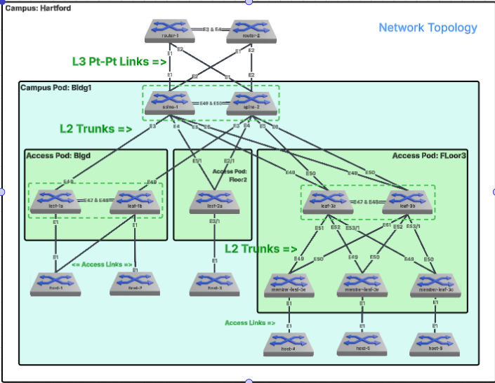
There are several Campus Architecture options. This guide is going to focus on a L2LS (Layer 2 Leaf Spine) design.
Lab Tasks – The Campus Fabric
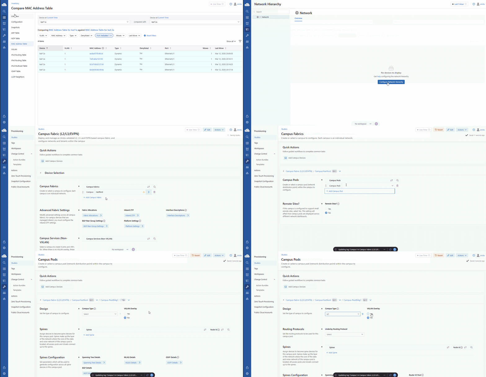
We are heading into Network Hierarchy to launch the Campus Fabric Studio. We’ll start by defining our location—Hartford—and our first Campus Pod, Bldg1. Think of a 'Campus Pod' as a logical management boundary, like a physical building.
We are selecting L2 as our Campus Type, signaling to CloudVision that we want a classic Layer 2 distribution model where the default gateways are created on the Spines and the access layer stays simple.
- Select Network Hierarchy from the blue left panel.
- Click Configure Network Hierarchy to launch the Campus Fabric Studio.
- Add a Campus Fabric named Hartford. Click the blue arrow to the right of the name.
- A workspace will be created automatically.
- Add a pod named Bldg1. Click the blue arrow to the right.
- Set Campus Type to L2. Leave other settings as default.
Campus Pods can be thought of as a building, group of buildings, etc. Each campus pod will share a spine layer and will have one or more access pods. In this lab, we will treat Bldg1 as if it has multiple floors with multiple access pods.
Lab Tasks – Spines and Access Pods
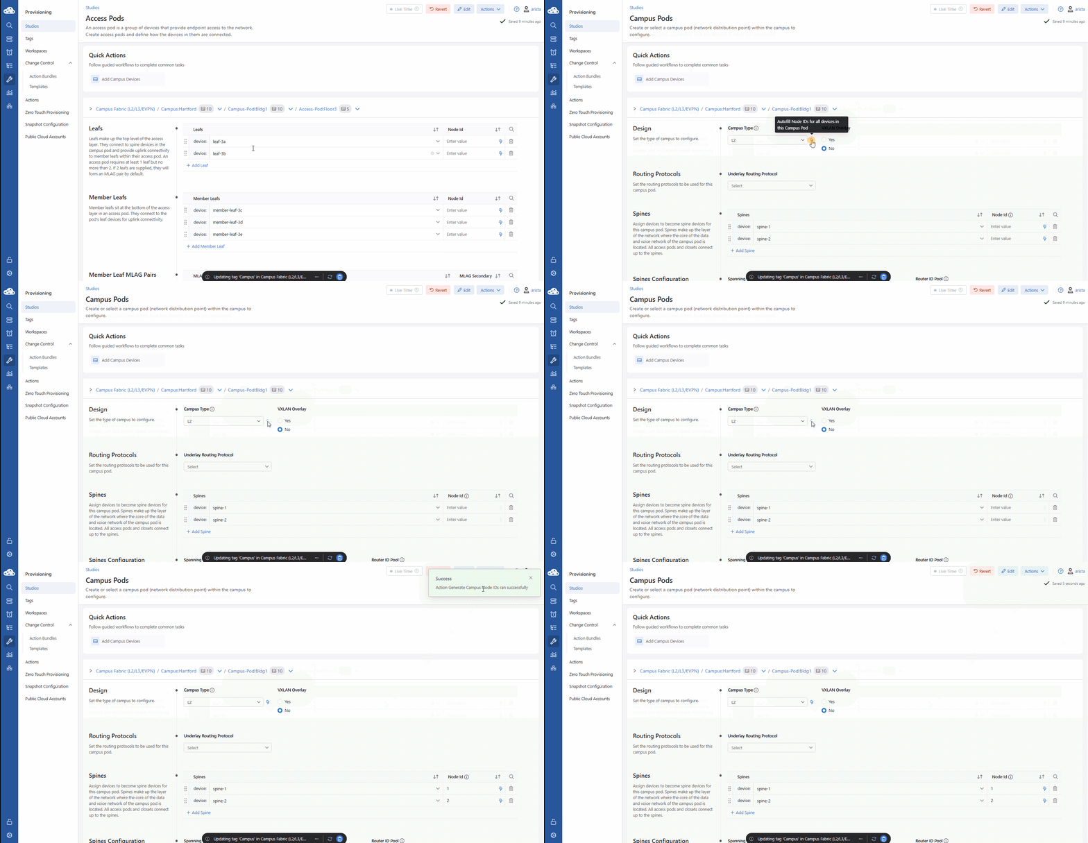
Now we’ll build the skeleton. We’re adding spine-1 and spine-2 as our core, then creating three Access Pods—one for each floor. As we add our leaves to these floors, notice the Campus Fabric Tree. This isn't just a list; it’s a visual representation of how your traffic will flow from the user on Floor 3 up to the Spines.
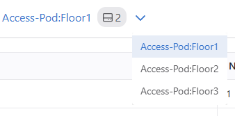
This line as the Campus Fabric Tree:

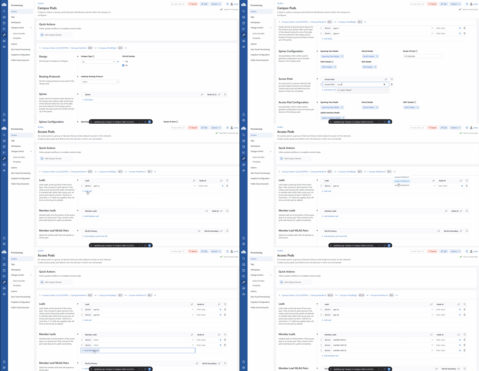
- Click Add Spine twice and select spine-1 and spine-2. Confirm the auto-assign tag prompt.
- Create three access pods by clicking Add Access Pod for each: Floor1, Floor2, and Floor3.
- Select the blue arrow for Floor1 and add Leafs: leaf-1a and leaf-1b (leave Node Id empty for now).
- Use the dropdown adjacent to Access-Pod:Floor1 in the Campus Fabric Tree to switch to Floor2.
-
Add leaf-2a.
-
Switch to Floor3. Add Leafs leaf-3a, leaf-3b and Member Leafs member-leaf-3c, 3d, and 3e.
Lab Tasks – Node assignments
Click that Lightning Bolt icon. This is a high-value automation step. CloudVision is now assigning unique Node IDs to every switch in the pod.
The Node Id uniquely identifies a switch in a campus pod. This number will determine the in-band management IP assigned to the device. Manipulating this value grants you control over the management IP of the switch.
- Click Campus-Pod:Bldg1 in the blue Campus Fabric Tree (upper blue text).
- Click the Lightning Bolt icon ⚡️ to the right of the Campus Type selector to automatically assign Node IDs.
Lab Tasks – Inband Management
Many campuses do not have a dedicated out of band management network to utilize the management interfaces on Arista switches, so CloudVision Studios is able to assign inband management addresses.
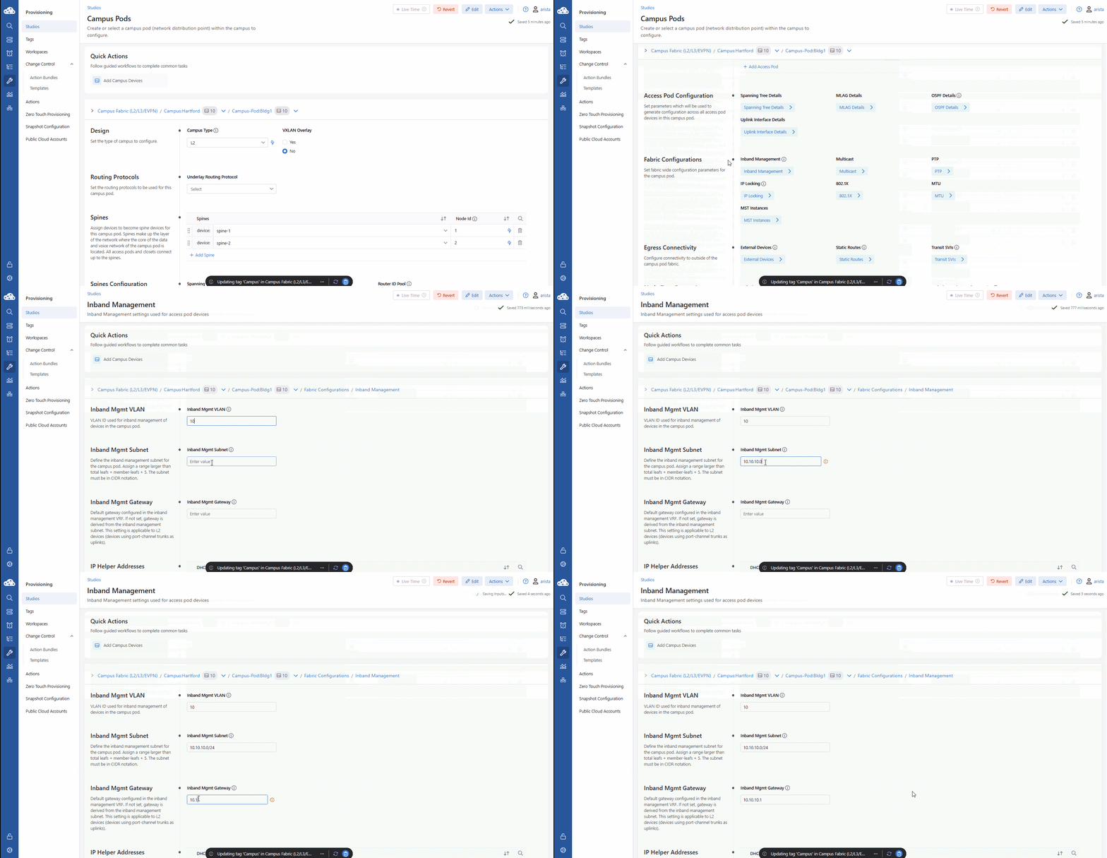
We’re setting up Inband Management on VLAN 10. By defining our subnet and gateway here, CloudVision will automatically configure every switch to be reachable over the production data plane, giving us full control without the extra cabling cost.
- Stay on the Bldg1 page. Locate Fabric Configurations (left) and click the blue Inband Management box.
- Populate the following fields:
- Inband Mgmt VLAN: 10
- Inband Mgmt Subnet: 10.10.10.0/24
- Inband Mgmt Gateway: 10.10.10.1
Lab Tasks – Change Control Review and Submission
At this point you have successfully created an L2LS campus fabric that is ready to be reviewed through the change control process.
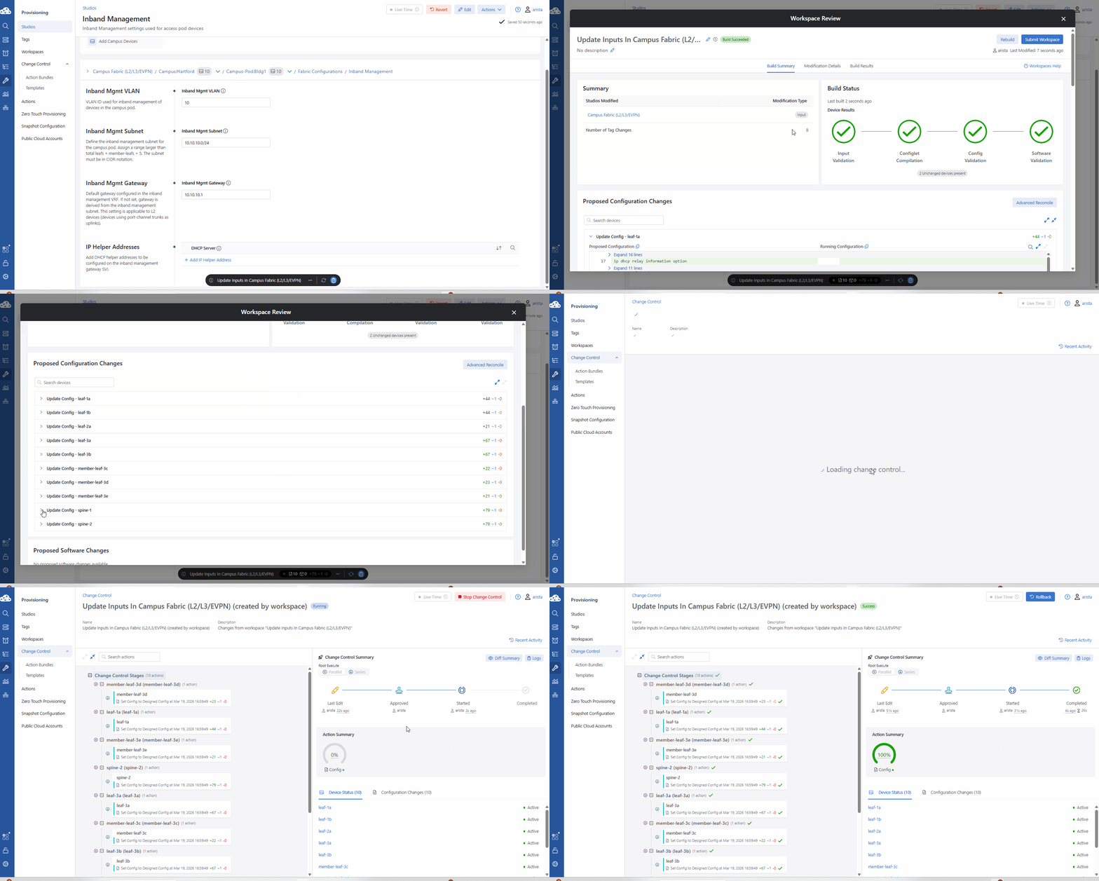
Your changes are currently 'staged'. They exist in the Studio but haven't touched the switches yet. When we hit Review and Submit on the Workspace Island, CloudVision runs a build to make sure our logic is sound. Once we move to Change Control, only when we click Approve and Execute, do we initiate the push of the 'Blueprint' to the 'Reality' of the hardware.
Change Controls are used to push configuration changes to your network. Workspaces can be created and abandoned without ever affecting the running configuration of your devices. You'll use Change Control to approve and execute changes that you've made in Workspaces to affect change on your network.
- On the Workspace Island, click the Review and Submit button (blue clipboard icon).
- Verify all Build Status checks pass.
- Scroll down in the workspace and take a look at the Proposed changes.
- Click Submit Workspace, then click View Change Control.
- Click Review and Approve (top-right).
- Notice how you are given a second chance to verify the proposed changes.
- Toggle Execute immediately to ON, then click Approve and Execute.
Lab Tasks – Campus Services: Non-VXLAN
We’re adding our client VLANs: Data (110), Voice (120), and Guest (130). A key takeaway here: in an L2LS design, you’ll notice the VLANs are created on the Leaf switches, but the Virtual Router gateways are configured on the Spines. This centralizes your routing at the spine layer while keeping the access layer fast and lean.
- Return to Provisioning > Studios > Campus Fabric studio
- Scroll down, and click the arrow next to Campus Services (Non-VXLAN) > Hartford and then the arrow next to Bldg1.
- Set Campus Type to L2.
- Click + Add VLAN three times and enter the VLAN IDs (number).
- Click on VLAN ID number 110 or the blue arrow to the right.
- Only change the fields below, the rest can be left as their defaults:
| VLAN | Name | Pods | IP Virtual Router Subnet |
|---|---|---|---|
| 110 | Data | "Floor1, Floor2, Floor3" | 10.1.10.0/24 |
| 120 | Voice | "Floor1, Floor2, Floor3" | 10.1.20.0/24 |
| 130 | Guest | "Floor1, Floor2, Floor3" | 10.1.30.0/24 |
You’ll notice that you do not enter the IP address of your virtual router (VLAN gateway) here. This will be either the first (.1) or last (.254 in a /24) IP address in the subnet. This is configurable in the Services Allocations section.
Lab Tasks – Change Control Review and Submission 2
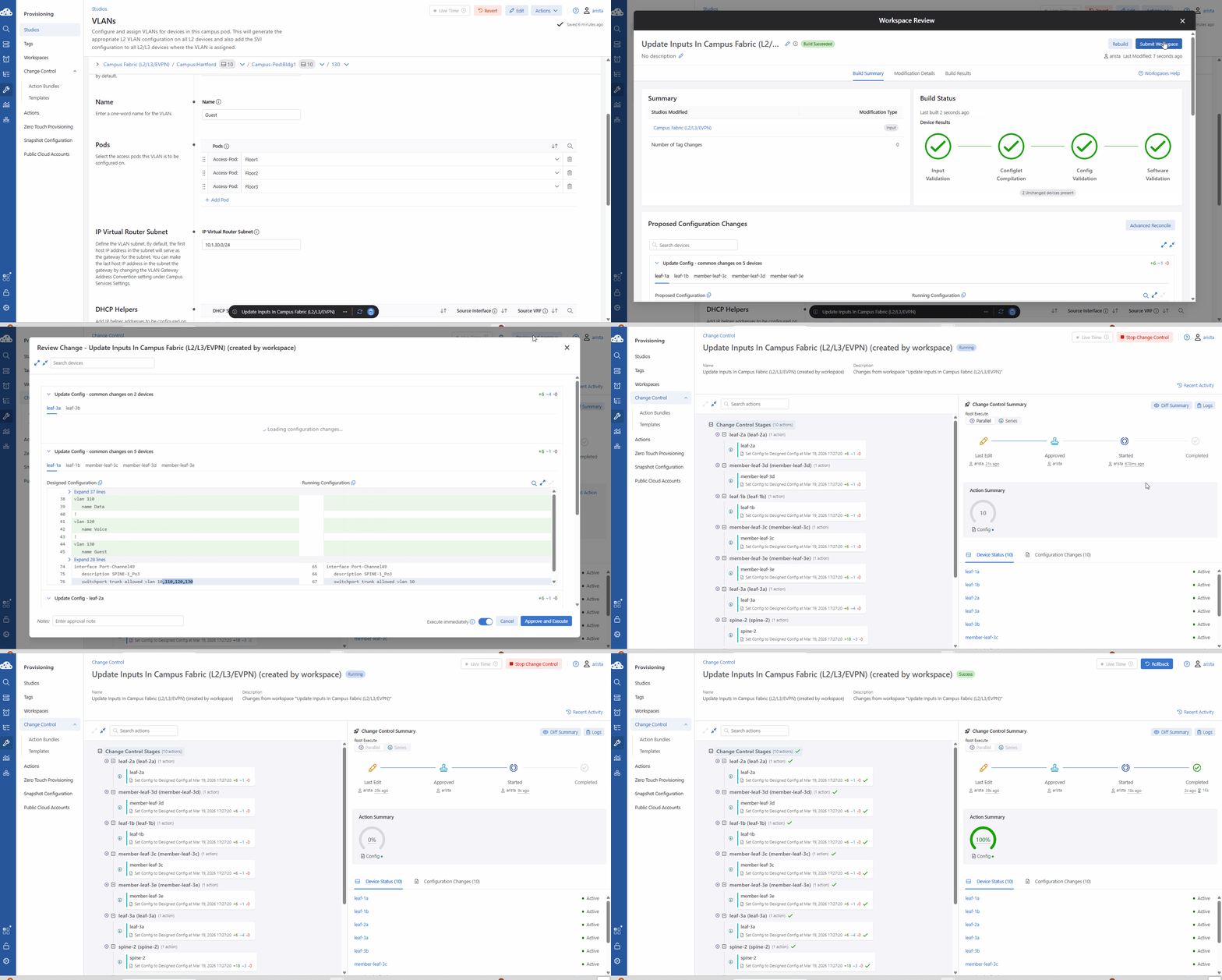
At this point you have successfully defined your client VLANs. This is a good example of a Day-1 operation. Submitting your workspace here will illustrate the proposed config changes that occur since your “underlay” has already been defined.
- On the Workspace Island, click the Review and Submit button.
- Verify all Build Status checks pass.
- Scroll down to review configurations.
- Notice how VLANs are created on the Leaf switches and the VLAN virtual-router addresses are configured on the Spine.
- This is due to the topology type selected (L2LS).
- Click Submit Workspace, then click View Change Control.
- Click Review and Approve (top-right).
- Toggle Execute immediately to ON, then click Approve and Execute.
Lab Tasks – Access Interface Configuration Studio
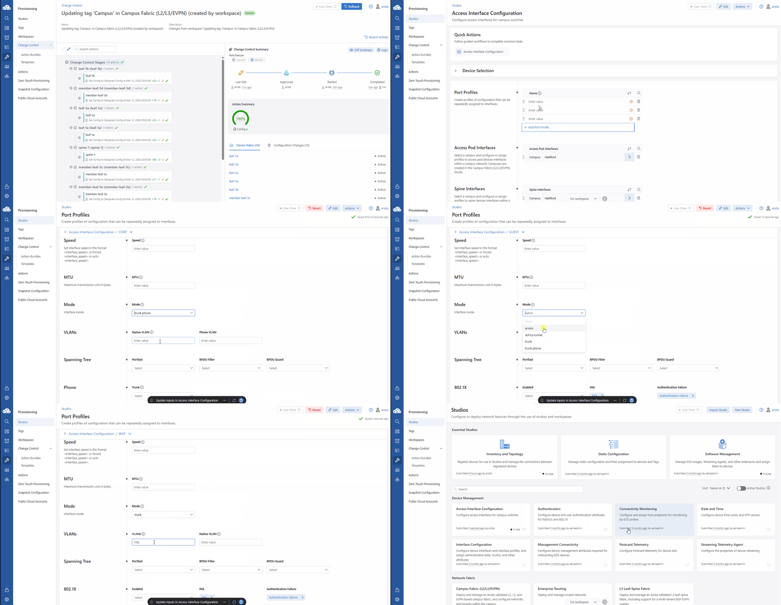
We’re moving to the Access Interface Configuration Studio to build our 'Port Profiles'. We’re creating templates for our Corporate PCs, Guest users, and Wireless Access Points. For example, the CORP profile uses 'trunk phone' mode to handle a PC and a Desk Phone on a single port.
When we submit this, notice there are no proposed changes. That’s because we’ve only built the 'Library' of profiles—in the next lab, we’ll actually assign these templates to the physical ports.
- Navigate to Provisioning > Studios.
- Open the Access Interface Configuration studio.
- If you do not see this, make sure to click the blue toggle next to Active Studios to unhide unused Studios.
- Click Add Port Profile to create three profiles: CORP, GUEST, and WAP.
- Click the > next to each profile and enter these details:
| Name | Description | Mode | VLANs | Native VLAN | Phone VLAN |
|---|---|---|---|---|---|
| CORP | Corp Trunk | trunk phone | - | 110 | 120 |
| GUEST | Guest VLAN | access | 130 | - | - |
| WAP | AP Trunk | trunk | "110, 130" | - | - |
- On the Workspace Island, click Review and Submit.
- No changes will be proposed as part of this change, we are building the profiles CloudVision will use to push config to devices.
- Once validated, click Submit Workspace and then Clear Workspace.
Congratulations, you have successfully completed your tasks. You can move on to the next lab.