Layer 2 Leaf-Spine
Guide Info
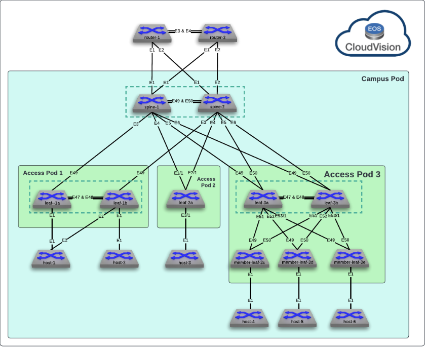
This lab will guide you through setting up a layer 2 leaf-spine architecture. Many of the concepts learned can be used to effectively deploy such a design in a production environment. This lab has been limited to the following devices: leaf-1a, and leaf-3a. Additional devices on this topology are out of scope for this lab.
Preparing The Lab
- Baseline your lab environment:
- Click on
Console Accesson the top left of your lab menu. - Type
l2lsand hit enter at the prompt. - The script will pre-configure the topology with the exception of leaf-1a and leaf-3a. leaf-3a will be configured manually, via the CLI, and then leaf-1 we will configure via Cloudvision to deomonstrate how we can effectively deploy configurations at scale with consistency.
- Click on
Lab Tasks
Before beginning, verify the MLAG operational details on leaf-3b. Since there is no current configuration on leaf-3a, the MLAG peer in this scenario, the MLAG state will be inactive. The output of show mlag will look similar to the example below.
Command Completion
In this guide the completed commands will be used for reference however the shortened commands are available. As an example show version and sh ver will produce the same output. Tab completion can be used as well.
Commands
Example
leaf-3b#show mlag
MLAG Configuration:
domain-id                          :            Access_Pod3_AGG
local-interface                    :            Vlan4094
peer-address                       :         10.1.255.10
peer-link                          :      Port-Channel47
peer-config                        :

MLAG Status:
state                              :            Inactive
negotiation status                 :      Lowerlayerdown
peer-link status                   :                  Up
local-int status                   :                  Up
system-id                          :   00:00:00:00:00:00
dual-primary detection             :            Disabled
dual-primary interface errdisabled :               False

MLAG Ports:
Disabled                           :                   4
Configured                         :                   0
Inactive                           :                   0
Active-partial                     :                   0
Active-full                        :                   0
leaf-3b#show mlag interfaces

  mlag     desc                       state     local     remote         status
-------- ----------------------- ------------ --------- ---------- ------------
    49     SPINES_Po5              disabled      Po49          -           up/-
    51     MEMBER-LEAF-3C_Po49     disabled      Po51          -           up/-
    52     MEMBER-LEAF-3D_Po49     disabled      Po52          -           up/-
   531     MEMBER-LEAF-3E_Po49     disabled     Po531          -           up/-
CLI Configuration - leaf-3a
Configure the MLAG domain on leaf-3a using the following steps:
-
Configure the layer 2 VLAN MLAG communication between the peer switches
Trunk Group
Arista best practices leverage a
trunk groupto limit layer 2 forwarding of the MLAG peering VLAN to only the peer-link, which we will see later. This is because we also recommend disabling STP operation on the MLAG peering VLAN to ensure MLAG adjacency can form immediately as EOS comes up without waiting for the STP learning process to complete.Commands
Example
-
Configure the MLAG Peer-link Port-Channel on leaf-3a to connect to leaf-3b
MLAG Trunks
Here, the trunk group applied to the MLAG peering VLAN is applied to the peer-link to ensure the MLAG VLAN is only forwarded on this link. Note we also can do interface ranges and groups when applying similar configurations as shown. Member interfaces of a port-channel will inherit all configuration of the parent so there is no need to apply things like switchport commands to the individual interfaces.
Commands
configure
interface Port-Channel47
description MLAG_Peer_leaf-3b_Po47
switchport mode trunk
switchport trunk group MLAG
!
interface Ethernet 47
description MLAG_PEER_leaf-3b_Ethernet47
channel-group 47 mode active
no shutdown
!
interface Ethernet 48
description MLAG_PEER_leaf-3b_Ethernet48
channel-group 47 mode active
no shutdown
Example
leaf-3a#configure
leaf-3a(config)#interface Port-Channel47
leaf-3a(config-if-Po47)#   description MLAG_Peer_leaf-3b_Po47
leaf-3a(config-if-Po47)#   switchport mode trunk
leaf-3a(config-if-Po47)#   switchport trunk group MLAG
leaf-3a(config-if-Po47)#!
leaf-3a(config-if-Po47)#interface Ethernet 47
leaf-3a(config-if-Et47)#   description MLAG_PEER_leaf-3b_Ethernet47
leaf-3a(config-if-Et47)#   channel-group 47 mode active
leaf-3a(config-if-Et47)#   no shutdown
leaf-3a(config-if-Et47)#!
leaf-3a(config-if-Et47)#interface Ethernet 48
leaf-3a(config-if-Et48)#   description MLAG_PEER_leaf-3b_Ethernet48
leaf-3a(config-if-Et48)#   channel-group 47 mode active
leaf-3a(config-if-Et48)#   no shutdown
Verification
Verify Port-Channel and L2 forwarding status
Commands From Anywhere
In EOS, any command can be run from any CLI mode. Here we can run show commands directly from interface configuration mode.
Commands
leaf-3a(config-if-Et48)#show interfaces status
Port       Name                         Status       Vlan     Duplex Speed  Type            Flags Encapsulation
Et47       MLAG_PEER_leaf-3b_Ethernet47 connected    in Po47  full   1G     EbraTestPhyPort
Et48       MLAG_PEER_leaf-3b_Ethernet48 connected    in Po47  full   1G     EbraTestPhyPort
Et49       SPINE-1_Ethernet5            connected    in Po49  full   1G     EbraTestPhyPort
Et50       SPINE-2_Ethernet5            connected    in Po49  full   1G     EbraTestPhyPort
Et51       MEMBER-LEAF-3C_Ethernet49    connected    in Po51  full   1G     EbraTestPhyPort
Et52       MEMBER-LEAF-3D_Ethernet49    connected    in Po52  full   1G     EbraTestPhyPort
Et53/1     MEMBER-LEAF-3E_Ethernet49    connected    in Po531 full   1G     EbraTestPhyPort
Ma0                                     connected    routed   a-full a-1G   10/100/1000
Po47       MLAG_Peer_leaf-3b_Po47       connected    trunk    full   2G     N/A
Po49       SPINES_Po5                   connected    trunk    full   4G     N/A
Po52       MEMBER-LEAF-3D_Po49          connected    trunk    full   2G     N/A
Po531      MEMBER-LEAF-3E_Po49          connected    trunk    full   2G     N/A
leaf-3a(config-if-Et48)#show interfaces trunk Port Mode Status Native vlan Po47 trunk trunking 1 Po49 trunk trunking 1 Po52 trunk trunking 1 Po531 trunk trunking 1 Port Vlans allowed Po47 All Po49 10,310,320,330 Po52 10,310,320,330 Po531 10,310,320,330 Port Vlans allowed and active in management domain Po47 1,10,310,320,330,4094 Po49 10,310,320,330 Po52 10,310,320,330 Po531 10,310,320,330 Port Vlans in spanning tree forwarding state Po47 1,10,310,320,330,4094 Po49 10,310,320,330 Po52 10,310,320,330 Po531 10,310,320,330 -
Configure the MLAG Layer 3 peering network
L3 MLAG Peering
The MLAG VLAN and peering network are used only for communication between the peer switches. As such, the IP network that is used does not need to be unique or routeable (though it can be if customers choose). In the lab, we reuse 10.1.255.10/31 on all MLAG pairs.
Commands
Example
leaf-3a(config-if-Et48)#configure
leaf-3a(config)#interface Vlan4094
leaf-3a(config-if-Vl4094)#   description MLAG_PEER
leaf-3a(config-if-Vl4094)#   mtu 1500
leaf-3a(config-if-Vl4094)#   no autostate
leaf-3a(config-if-Vl4094)#   ip address 10.1.255.10/31
Verification
Verify layer 3 connectivity between the peer switches on the MLAG VLAN.
Commands
Example
leaf-3a(config-if-Vl4094)#ping 10.1.255.11 80 bytes from 10.1.255.11: icmp_seq=1 ttl=64 time=2.19 ms 80 bytes from 10.1.255.11: icmp_seq=2 ttl=64 time=1.56 ms 80 bytes from 10.1.255.11: icmp_seq=3 ttl=64 time=1.58 ms 80 bytes from 10.1.255.11: icmp_seq=4 ttl=64 time=1.49 ms 80 bytes from 10.1.255.11: icmp_seq=5 ttl=64 time=1.64 ms --- 10.1.255.11 ping statistics --- 5 packets transmitted, 5 received, 0% packet loss, time 8ms rtt min/avg/max/mdev = 1.485/1.690/2.192/0.255 ms, ipg/ewma 2.078/1.933 ms -
Define the MLAG Domain parameters to establish the peering.
Commands
configure
!
mlag configuration
domain-id Access_Pod3_AGG
local-interface Vlan4094
peer-address 10.1.255.11
peer-link Port-Channel47
reload-delay mlag 300
reload-delay non-mlag 330
!
exit
Domain-Id
Similar to the peering network, the MLAG
domain-idcan be reused across pairs as it is a locally significant value. The other values describe the connectivity between the peer switches.Verification
Verify the MLAG relationship between leaf-3a and leaf-3b.
Commands
Example
leaf-3a#show mlag
MLAG Configuration:
domain-id                          :     Access_Pod3_AGG
local-interface                    :            Vlan4094
peer-address                       :         10.1.255.11
peer-link                          :      Port-Channel47
peer-config                        :        inconsistent

MLAG Status:
state                              :              Active
negotiation status                 :           Connected
peer-link status                   :                  Up
local-int status                   :                  Up
system-id                          :   02:1c:73:b7:c6:01
dual-primary detection             :            Disabled
dual-primary interface errdisabled :               False

MLAG Ports:
Disabled                           :                   0
Configured                         :                   0
Inactive                           :                   0
Active-partial                     :                   0
Active-full                        :                   3
leaf-3a#show mlag interfaces local/remote mlag desc state local remote status ---------- ------------------------- ----------------- ----------- ------------ ------------ 49 SPINES_Po5 active-full Po49 Po49 up/up 52 MEMBER-LEAF-3D_Po49 active-full Po52 Po52 up/up 531 MEMBER-LEAF-3E_Po49 active-full Po531 Po531 up/up -
Add a port-channel to connect to
member-leaf-3c. This is how you would add additional devices into your leaf-spine stack in a communications closet.Commands
configure
!
interface Port-Channel51
description MEMBER-LEAF-3C_Po49
no shutdown
switchport
switchport trunk allowed vlan 10,310,320,330
switchport mode trunk
mlag 51
!
interface Ethernet51
description MEMBER-LEAF-3C_Ethernet49
channel-group 51 mode active
no shutdown
!
Verification
Verify the MLAG interface to
member-leaf-3cis up/upCommands
Example
leaf-3a#show mlag interfaces
                                                                                local/remote
mlag       desc                            state       local       remote          status
---------- ------------------------- ----------------- ----------- ------------ ------------
    49       SPINES_Po5                active-full        Po49         Po49           up/up
    51       MEMBER-LEAF-3C_Po49       active-full        Po51         Po51           up/up
    52       MEMBER-LEAF-3D_Po49       active-full        Po52         Po52           up/up
    531      MEMBER-LEAF-3E_Po49       active-full       Po531        Po531           up/up
Connect to
member-leaf-3cand validate connectivity frommember-leaf-3ctomember-leaf-3d.Commands
Example
member-leaf-3c#ping 10.10.10.12
PING 10.10.10.12 (10.10.10.12) 72(100) bytes of data.
80 bytes from 10.10.10.12: icmp_seq=1 ttl=64 time=10.3 ms
80 bytes from 10.10.10.12: icmp_seq=2 ttl=64 time=2.20 ms
80 bytes from 10.10.10.12: icmp_seq=3 ttl=64 time=2.34 ms
80 bytes from 10.10.10.12: icmp_seq=4 ttl=64 time=2.39 ms
80 bytes from 10.10.10.12: icmp_seq=5 ttl=64 time=2.19 ms

--- 10.10.10.12 ping statistics ---
5 packets transmitted, 5 received, 0% packet loss, time 35ms
rtt min/avg/max/mdev = 2.187/3.893/10.349/3.228 ms, pipe 2, ipg/ewma 8.786/7.009 ms
Connect to
spine-1and verify layer 2 forwarding informationCommands
Example
spine-1#show mac address-table vlan 110
        Mac Address Table
------------------------------------------------------------------

Vlan    Mac Address       Type        Ports      Moves   Last Move
----    -----------       ----        -----      -----   ---------
 110    001c.7300.dc01    STATIC      Cpu
 110    001c.73b3.c601    STATIC      Po491
 110    1ad4.d511.62f4    DYNAMIC     Po5        1       0:08:53 ago
 110    423b.b85a.b923    DYNAMIC     Po5        1       0:03:55 ago
Total Mac Addresses for this criterion: 4

        Multicast Mac Address Table
------------------------------------------------------------------

Vlan    Mac Address       Type        Ports
----    -----------       ----        -----
Total Mac Addresses for this criterion: 0
Success
CLI Driven L2LS Lab Complete!
Additional Testing
Explore optional command output related to MLAG operation on leaf-3a.

MLAG Detail
The show mlag detail output contains a wealth of information. Notice that while there is a primary and secondary role for the MLAG peers, it is not a configurable value. The peers automatically negotiate this between themselves. The MLAG primary device is responsible for all STP processing for both peers. The Reload delay value is also very important in upgrade and maintenance scenarios.
Commands

leaf-3a only to see how MLAG tracks consistency between the peer switches.
MLAG Config-Sanity
It is critical that the MLAG peers be consistent to ensure proper forwarding and operation. The show mlag config-sanity command helps to track values that are not consistent. These values should be rectified in production environments unless guided otherwise by an Arista SE.
Commands
Example
No per interface configuration inconsistencies found.

Global configuration inconsistencies:
    Feature                   Attribute       Local value    Peer value
-------------- --------------------------- ----------------- ----------
   bridging        admin-state vlan 999            active             -
   bridging       mac-learning vlan 999              True             -
Notice in the output there is a Local value of active/True for VLAN 999 however this is not true for the peer, leaf-3b. Now, remove vlan 999 to see what occurs.
Cloudvision Provisioning - leaf-1a
Accessing Cloudvision in the Lab
Navigate to the topology overview page. The unique, per environment, username and password will be at the bottom of the page. On the left panel, click CVP. From the CVP login screen, enter your username and password. Please allow up to 15~20 minutes for CVP to completely build and deploy the base configurations.
The only remaining portion of the L2LS fabric is applying the configuration to leaf1-a. By using Arista's UI driven multi-purpose helper, Cloudvision, network administrators can easily automate configuration management and have near real-time insights into the device telemetry.
Arista Tech-Library
For more detailed information into all of the capabilities that Cloudvision provides, Arista customers can access the Tech-Library at arista.com/en/tech-library. Here there will be deep dives on various aspects of the Arista portfolio along with guides on how to deploy these technologies in a production environment.
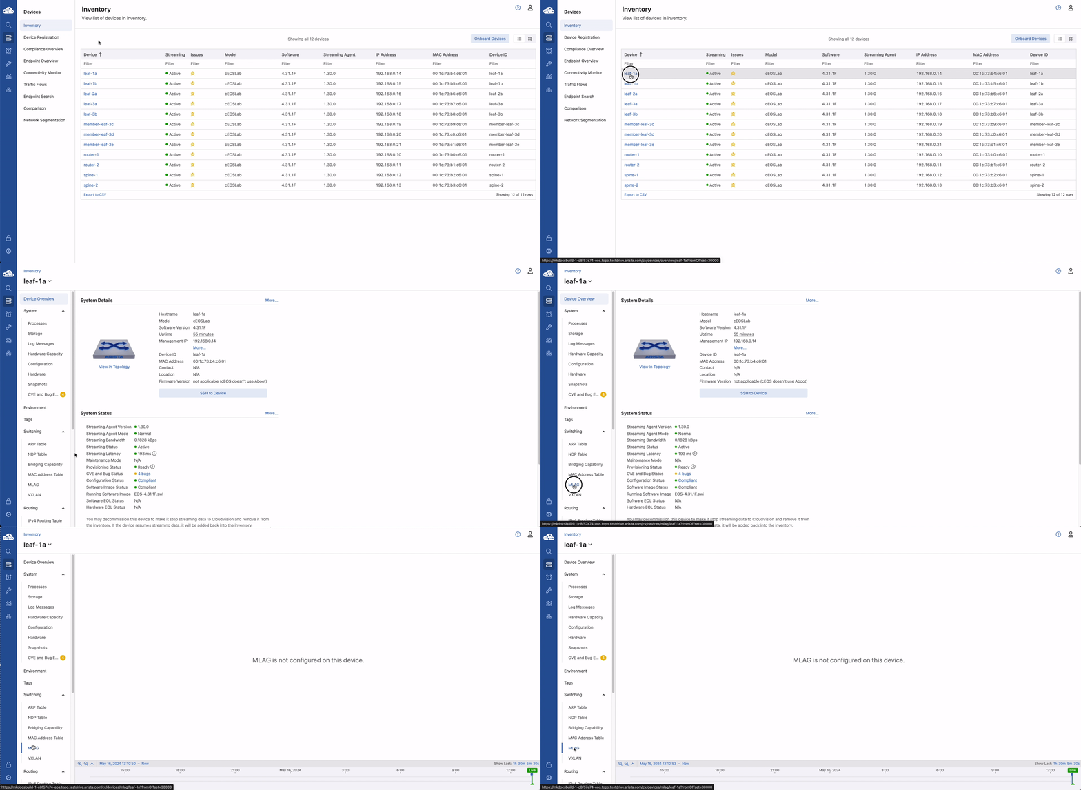
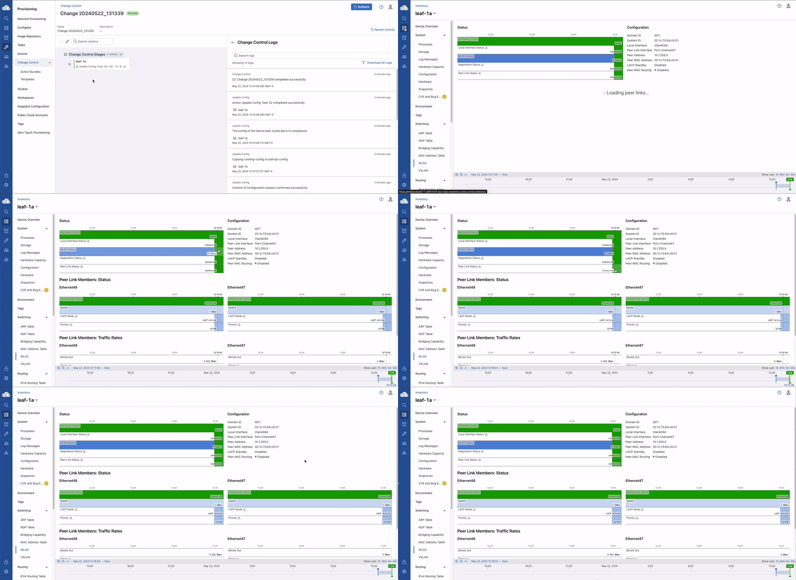
The initial landing page for Cloudvision will be the device inventory page. Left-click on leaf-1a and midway down the left panel select Switching > MLAG. Notice that MLAG is not currently configured.
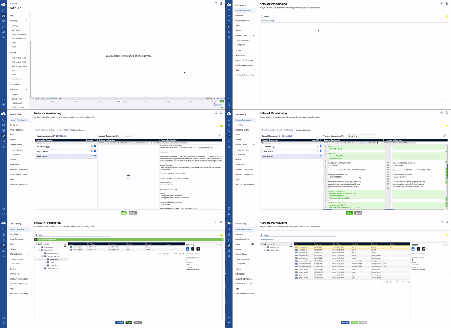
Hover over the wrench on the left navigation panel and switch to the provisioning tab. Right click on the leaf-1a.atd.lab. Select Manage > Configlet. This will now list all available configlets, as well as the configlets that have been applied to the device. Click the checkbox next to L2LS_leaf-1a and then Validate near the bottom of the screen. The configuration that will be added is highlighted in green. Finally click save and then click save again which will generate a task.
Configlets
Configlets are snippets of device configuration. By splitting the device configuration into chunks, we can combine those to create the full designed and/or running configuration of the device. This also allows the capability of configuration hierarchy so that configuration can be inherited from higher levels. As an example, you can right click on the Tenant and see the ATD-INFRA configlet that has been applied. PLEASE DO NOT MAKE CHANGES TO THIS CONFIGLET. IT WILL BREAK THE LAB
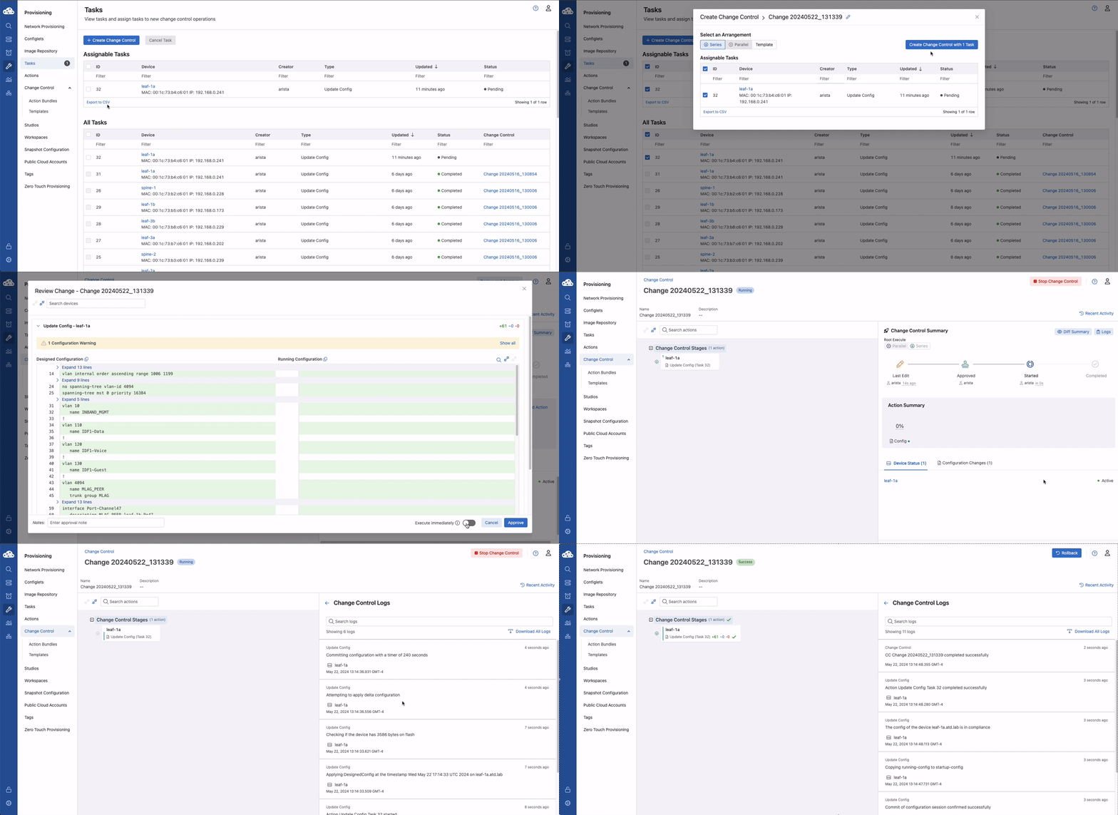
Click tasks. There is now one assignable task for leaf-1a. Click the check box to the left and then Create Change Control. In the pop up, click Create Change Control with 1 Task. Click Review and Approve at the top right of the screen. This is a final opportunity to review the configuration changes that will be made to the device. These changes can be scheduled to execute at a future time/date or executed immediately with the toggle at the bottom. Toggle Execute Immediately to true and then approve and execute. The changes will be pushed to the device.
Finally, go to the device overview screen and review the MLAG status. The MLAG peer connection should now be connected.
Success
Lab Complete!
Extra Credit
Create a configlet in Cloudvision for VLAN 670 and apply it to leaf-1a and leaf-1b.
