Lab 1 - Campus Network to ISP
Lab Summary
In this example, you’ll deploy a campus network that is connected to an ISP. Between the Campus and the ISP is an Edge Router (ER) acting as a network core/WAN router that runs OSPF to the Campus Splines and eBGP to the ISP. The BGP policy on the WAN router sends an Aggregate route to the ISP and sends only a default route to the Campus. Be sure to have read through the prep section above and have completed any tasks there.
Please look over the diagrams to get a feel for what we are about to configure.
This lab features:
- MLAG and virtual router address
- Routed interface and eBGP to external peer
- OSPF on Campus Splines
- OSPF to BGP redistribution
- Prefix list and BGP policy towards ISP
- OSPF default information originate
Configuring the Lab
You may have already completed some of the import steps during the lab setup, if so, you can skip to the deploy step.
-
Sanitize The Topology (only if you assigned other tags or did other Studios labs prior to this)
-
Run the tagman script for tagsfile-example1.txt.
python3 tagman.py -u arista -p YOUR_CVP_PASSWORD -c *unique-name*.topo.testdrive.arista.com -f tagsfile-example1.txt -a import -o add
Import Studio Inputs
-
Open the Campus Fabric Studio and click the ellipsis in the upper right corner beside Edit.
-
Select Import under the Inputs section, then navigate to the InterOp_Examples_for_Studios/Example1_Campus_to_ISP_BGP folder and import the file called Inputs_Campus Fabric
-
Repeat steps 1 and 2, but instead, click on the Enterprise Routing Studio, then import the Inputs_Enterprise_Routing file.
-
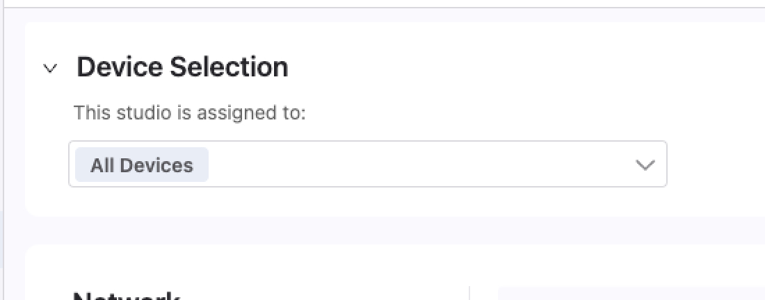
Under the Device Selection section of each Studio make sure All Devices is selected.
Deploy
-
We’re now ready to deploy the configuration we imported into Studios. To do this, click on Review Workspace
-
Studios will then begin building the configlets and validating them against the devices. When this completes, the Submit Workspace button will be available to click on.
-
After we click on Submit Workspace, a popup box will show us that the Change Control is being created. After this is finished, the View Change Control option is blue and we can click on it.
-
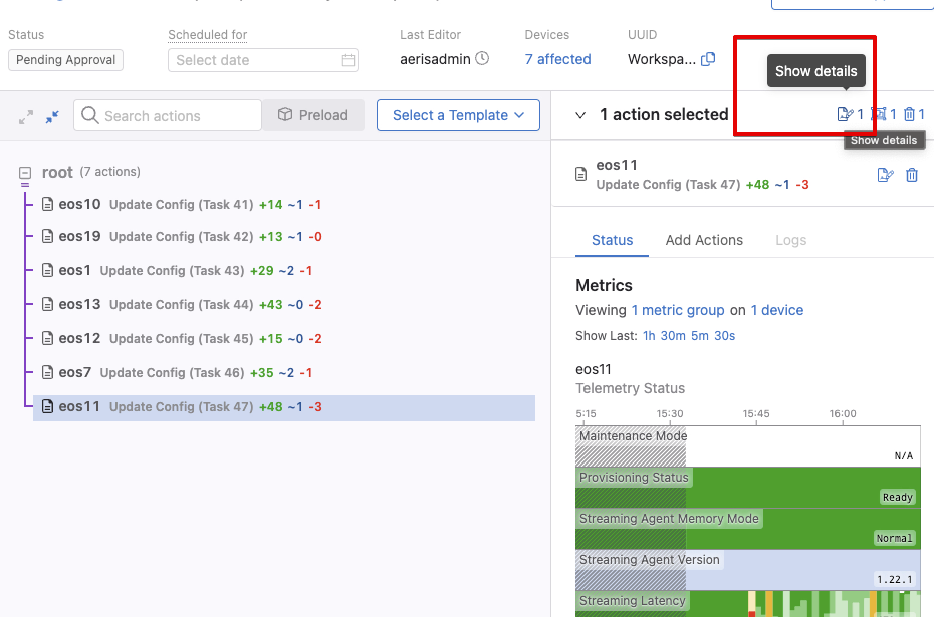
On the Change Control screen, we see a summary of the changes that will be pushed to each switch. We can click on a switch and select the Show Details button to see the exact lines that will be pushed to each switch.
Note
- You should see vlan 15 being created on the campus splines (
EOS11andEOS13) - VLAN 15 is a management VLAN in the campus studio. This makes it the native vlan and leaf switches will get a management IP address and default route
- You should see vlan 15 being created on the campus splines (
-
Use the Review and Approve button on the upper right, then the Approve and Execute button to push these changes to the switches.
-
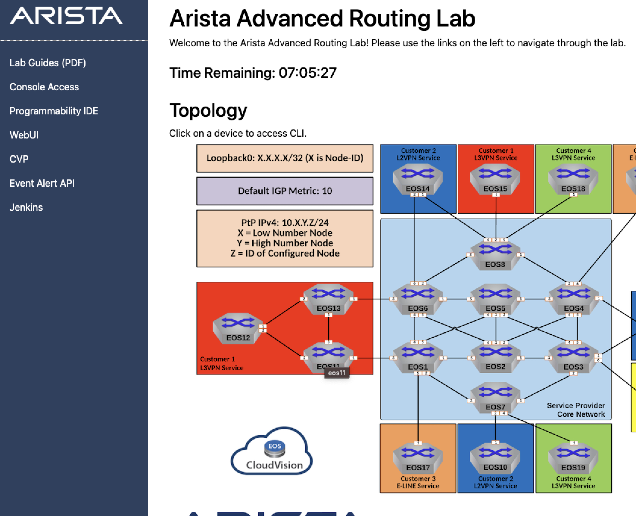
Back on the ATD landing page, click on
EOS11on the image to get to the terminal where you can run commands on the switch. -
If our Studio was successful, you should now see routes for 10.10.10.10 and 19.19.19.19 when you run show ip route.
Test
Test reachability within your topology by accessing the CLI on EOS12 and pinging 10.10.10.10 (EOS10) and 19.19.19.19 (EOS19)
Lab Tasks
-
Source a default route from
EOS1to block the specific routes coming from the ISP.-
In the Enterprise Routing Studio find the Core Router
EOS1and enter the page for the BGP Peer Group. -
Enable OSPF Default Information Originate Always Send and add a deny filter in the redistribute route map that prevents the Internet routing detail from entering the Campus.
-
Verification - Use the ATD’s configuration screen to access a CLI for the below devices:
-
From
EOS12, ping 10.10.10.10 (EOS10) and 19.19.19.19 (EOS19) -
Verify that
EOS11andEOS13have a default route and no longer have 10.10.10.10 and 19.19.19.19 in their routing table.
-
-
-
Learning hiding and Showing UI fields in a Studio.
-
Go to the Enterprise Routing Studio and the ISP Network.
-
Notice there is a OSPF specific MAX LAA field at the bottom of the page even though ISIS is being used by the ISP, so this setting does not apply to ISIS.
-
Edit this Studio to hide OSPF MAX LSA field and only show it when OSPF is selected.
-
-
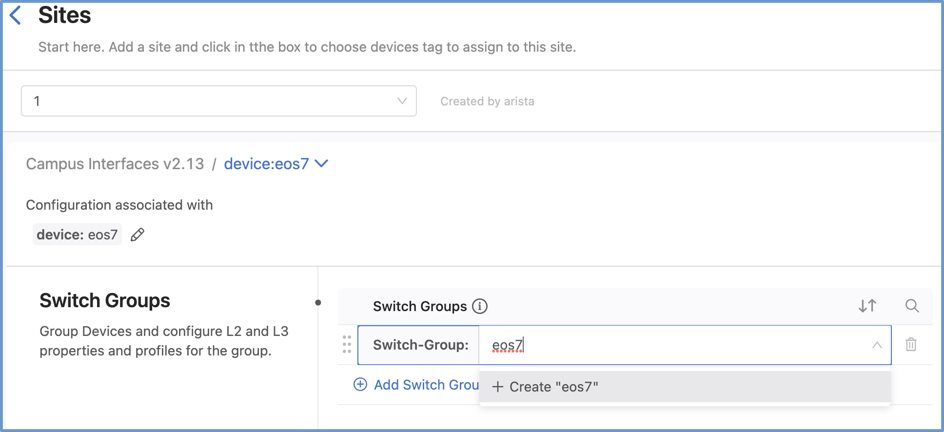
Add a Port Mirror session to
EOS7. We will use the Campus Interfaces Studio for this task.-
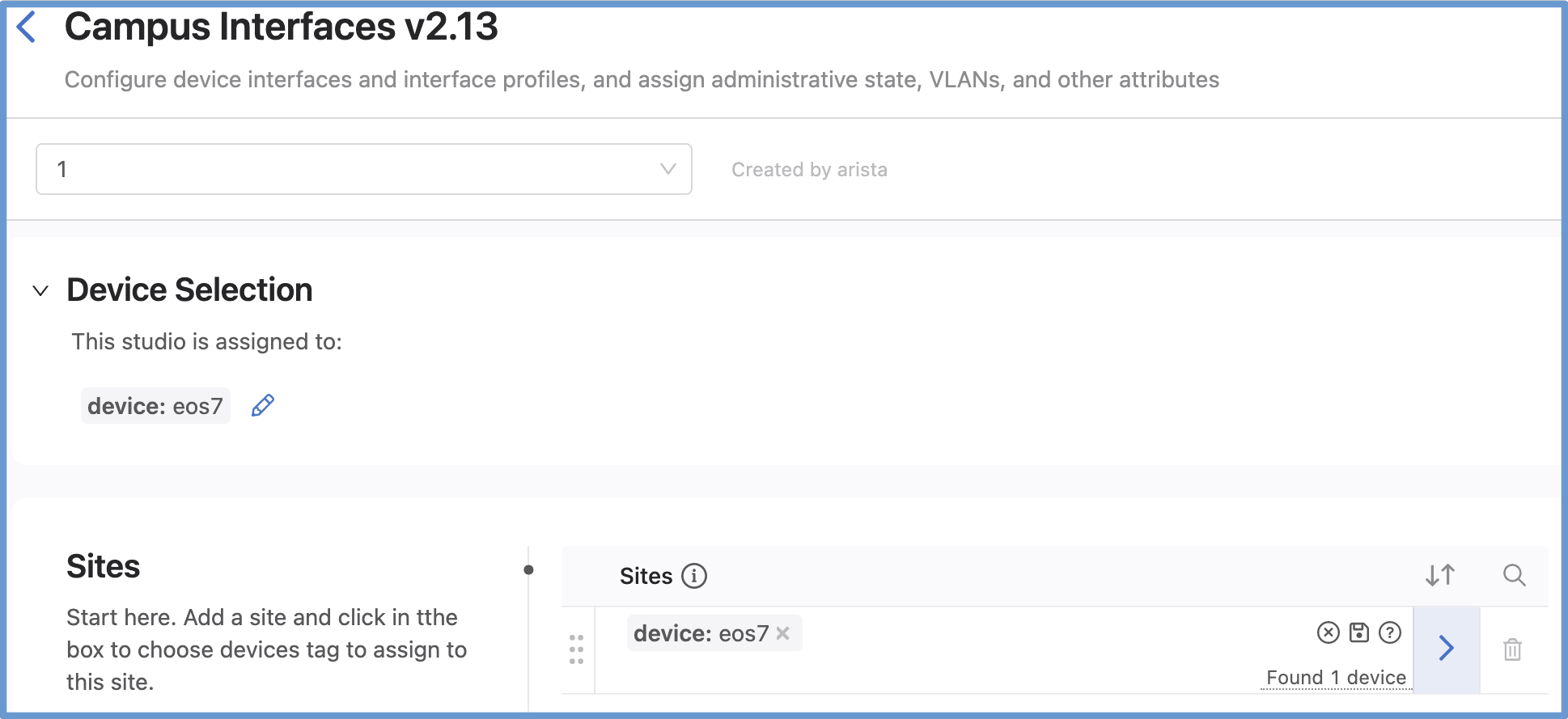
Add a Site and select tag
device:eos7. -
Add a switch-group tag to
EOS7called switch-group: eos7. -
Click the arrow and at the top of the next page add
EOS7to the Assigned Devices box. -
Add at the bottom of the page configure your Port Mirror session and build the workspace.
-
Yikes! cEOS does not support the port mirroring feature.
-
Success
Lab Complete! Before moving on to Lab 2 remember to sanitize your topology first.

