Prepare to Offer VPN Services to Customers via MP-BGP EVPN Control-Plane
Preparing The Lab
- Log into the LabAccess jumpserver:
- Type
labs, or select Option 97 to get to theAdditional Labsmenu. - Type or select the option for
ring-topology-evpn-labsin order to get to the EVPN labs. - Type
evpnin this menu to configure the topology with the necessary prerequisites.
- Type
Lab Tasks
-
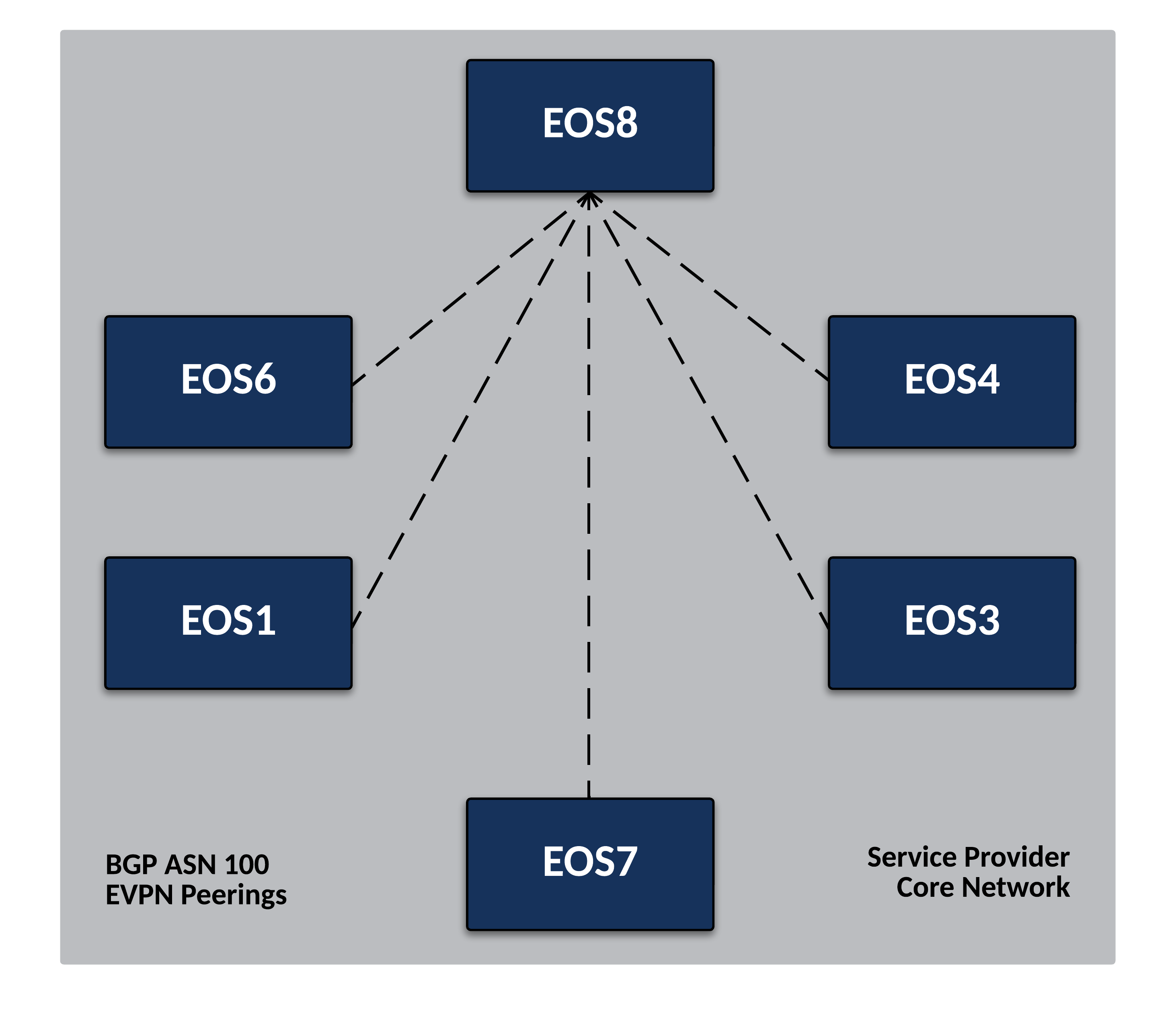
We will now leverage BGP as the control-plane for our VPNs in the Service Provider network. Specifically, we will use iBGP with a Route Reflector to ease the configuration load and not require us to setup a full mesh of BGP peerings. Configure
EOS8as the Route Reflector in the Service Provider Network.-
On
EOS8, enable BGP with ASN 100. Also set a router-id and disable the IPv4 Unicast Address-Family within BGP.Info
By default, all BGP neighbors in EOS will try to peer in the IPv4 Unicast AF. Since we are only leveraging BGP for VPNs and IS-IS is providing our IPv4 underlay, there is no need for this additional overhead. We can change the default state of BGP to not attempt to peer using the IPv4 Unicast AF.
-
Allow BGP to utilize ECMP when available by increasing the Maximum Paths allowed for a route.
Info
By default, BGP will only install a single best-path. In a network with multiple equal paths available, this setting will allow BGP to load balance across the available paths. This is covered further in a later lab.
-
Activate the EVPN address-family within BGP and set the data-plane encapsulation type to MPLS.
Info
EVPN will provide a signaling mechanism for all our L2, L3 and wire services in the Service Provider network. By default, EOS will leverage VXLAN as a data-plane encapsulation for EVPN. We can again change the default behavior according to our desired architecture.
-
To simplify BGP configuration, create a peer group to apply common BGP attributes to the other EOS nodes in the Service Provider network that will act as Route Reflector Clients. We will peer using iBGP as mentioned and use the router Loopback0 interfaces as the source. Ensure that standard and extended BGP communities and the EVPN address-family are enabled for this peer-group as well.
Info
In EOS, the send-community command alone will send all communities. You can selectively enable them if you would prefer to send only extended. EVPN requires the use of extended communities. Also note that EOS by default includes a maximum-routes setting of 12,000 for all BGP peers to prevent a peer from sending more routes than expected. This value can be changed per network requirements.
router bgp 100 neighbor PE-RRCLIENTS peer group neighbor PE-RRCLIENTS remote-as 100 neighbor PE-RRCLIENTS update-source Loopback0 neighbor PE-RRCLIENTS route-reflector-client neighbor PE-RRCLIENTS send-community neighbor PE-RRCLIENTS maximum-routes 12000 ! address-family evpn neighbor PE-RRCLIENTS activate -
Finally, apply the peer group to the necessary routers in the Service Provider network.
Note
Since BGP EVPN is only providing our VPN control-plane, only Provider Edge (or PE) nodes, which are nodes attached to customer devices, will require the BGP peering. This is in contrast to Provider (or P) nodes, which only connect to other Service Provider nodes. In this topology, all active nodes are functioning as PE so will require BGP EVPN peerings to the Route Reflector.
-
Verify configuration on
EOS8. Since the other routers are not yet configured, there will be no peerings to check as of yet.
-
-
Now configure the PE nodes in the Service Provider network as the Route Reflector clients.
- Again, this will be iBGP and the peerings will look very similar to the setup on
EOS8. However, we will not need to leverage a peer group as all PE nodes will only peer with the route-reflector. The below example is forEOS1. Repeat this for all other Service Provider nodes with the exception ofEOS2andEOS5, changing the router-id to match Loopback0.
Note
On PE nodes, you will see a slightly different EVPN configuration when enabling MPLS as the data-plane. Since these routers are originating VPNs, we want to ensure they set themselves as the next-hop in BGP when advertising them.
router bgp 100 router-id 1.1.1.1 no bgp default ipv4-unicast maximum-paths 2 neighbor 8.8.8.8 remote-as 100 neighbor 8.8.8.8 update-source Loopback0 neighbor 8.8.8.8 send-community neighbor 8.8.8.8 maximum-routes 12000 ! address-family evpn neighbor default encapsulation mpls next-hop-self source-interface Loopback0 neighbor 8.8.8.8 activate - Again, this will be iBGP and the peerings will look very similar to the setup on
Testing
Once all other PE nodes are configured, verify BGP peerings are in place.
All PE nodes will only have one BGP peer, while the EOS8 as the route-reflector will peer with all other PE nodes. You will see the peerings as Established but no routes should be exchanged as no VPNs are configured. Also note that the standard show ip bgp summary command should have no output since the IPv4 unicast AF is not activated.
Success
Lab Complete!
