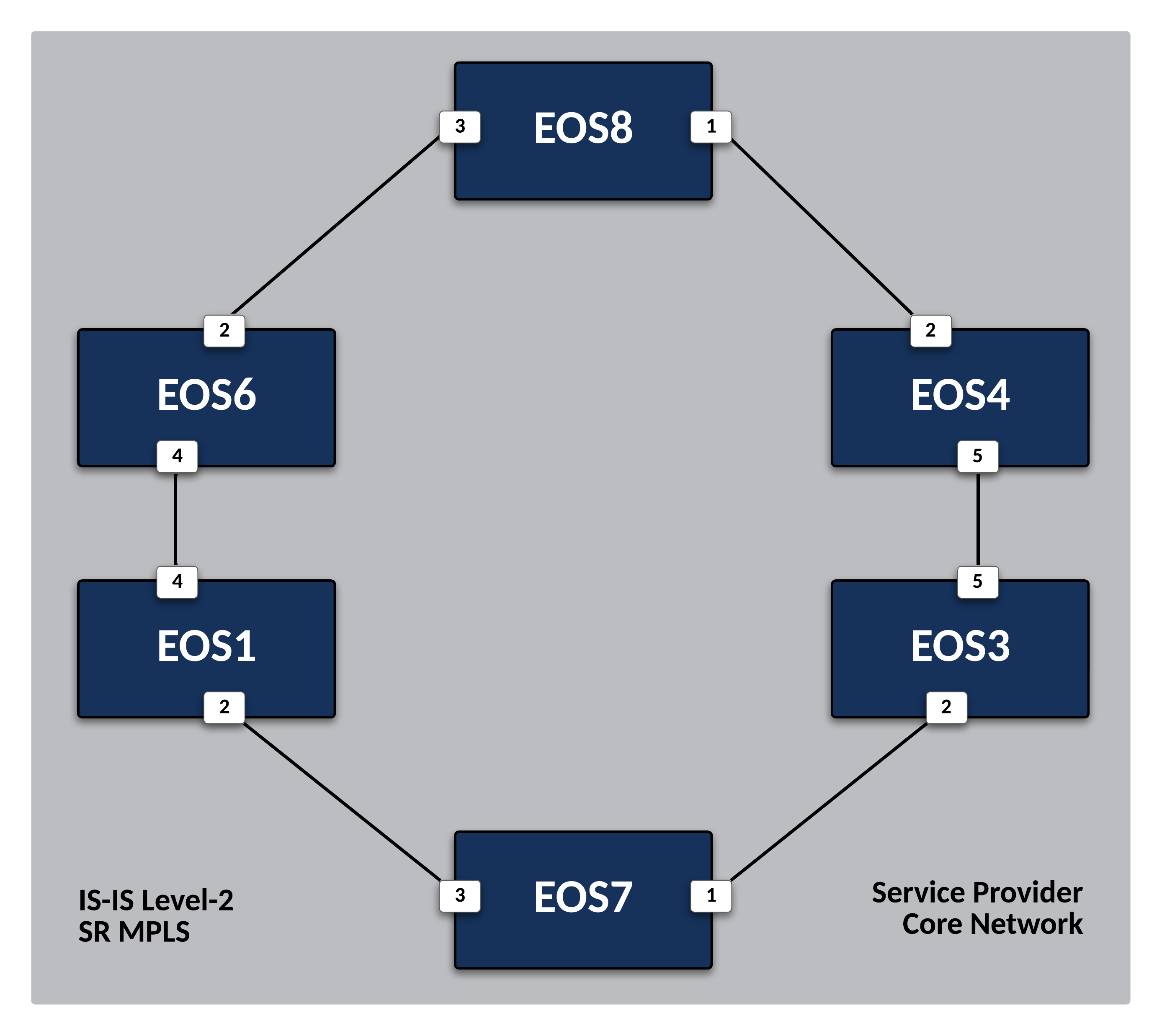
Deploy IS-IS as the Service Provider Underlay IGP
Note
The Base Labs of the Routing ATD are structured to build on each other. You should complete all Base Labs before moving onto Supplemental Labs. Alternatively, using the Lab Selection Menus will complete configurations for prior labs as necessary. Supplemental Labs can be completed in any order.
Preparing The Lab
-
Log into the LabAccess jumpserver:
- Type
labs, or select Option 97 to get to theAdditional Labsmenu. - Type or select the option for
ring-topology-evpn-base-labsin order to get to the EVPN labs. - Type
resetin this menu to configure the topology with the necessary prerequisites.
Did You Know?
The
resetoption (and all other options) makes use of CloudVision Portal APIs to apply configlets to each EOS node ensuring they have the proper configuration. - Type
Verification
Before starting any configuration, we want to check and verify the topology's base status on EOS1.
-
Verify interface configurations and neighbors:
Command Syntax
Full commands will be typed for reference in lab steps, but commands in EOS can be shortened or tab-completed at the user’s discretion.
-
Verify there is no routing protocol configuration or neighbors present as of yet:
Lab Tasks
-
Configure the IS-IS routing protocol on
EOS1using the following steps:-
Enable IS-IS with an instance ID of 100 and define a NET (1). For the NET, use the format of
49.1111.0000.000(EOS ID).00where 1111 is the IS-IS area ID and 0000.000 (EOS ID) is the System ID.- Network Entity Title
Note
Arista EOS utilizes the Industry-Standard CLI. When entering configuration commands, be sure to first type configure to enter configuration mode.
-
Set the IS-IS level to level-2 and activate the IPv4 unicast address-family to ensure the router will hold all backbone IPv4 routes.
Note
Our topology will maintain only IS-IS level-2 adjacencies. This will give us a single backbone area where all routes will be learned by all routers (similar to an OSPF topology where all routers are in area 0). This is sufficient for smaller topologies where there isn’t a need to segment flooding domains.
-
To shrink the overall size of the LSDB and routing table, we will only advertise Loopback /32 networks to other EOS routers and not individual link addressing. This is accomplished by only advertising passive IS-IS interfaces and networks.
-
Verify protocol configuration thus far.
Pro Tip
You do not need to
exitconfiguration mode to execute show commands in EOS.
-
-
Configure IS-IS interfaces on
EOS1:-
All links connecting to other SP routers (
EOS1throughEOS8) will form IS-IS adjacencies. Configure the link betweenEOS1andEOS7as an IS-IS interface. -
Additionally, since this is point to point link to a level-2 router, we will define those characteristics to ensure proper peering and bypass unnecessary DIS elections.
-
Repeat the above configurations for the other interfaces on
EOS1that are attached to adjacent SP nodes. Refer to the diagram above and LLDP neighbor information for interfaces requiring configuration.Pro Tip
You can configure multiple interfaces at once using ranges and separators in EOS. For example,
EOS1interfaces Et2 and 4 require IS-IS configuration, but the commands are the same for all interfaces. You can type interface Ethernet2,4 to enter configurations for all three at once. -
Next, the Loopback0 interface needs to be activated as an IS-IS interface.
-
Lastly, since Loopback0 is not attached to another router, we can set it as a passive interface for IS-IS to ensure proper operation.
Note
In addition, this command works in conjunction with the advertise passive-only command in our IS-IS protocol configuration. It ensures only our passive (i.e. Loopback0) interfaces will be advertised.
-
-
Since no other devices have been configured, there are no peers as of yet. Configure
EOS7using the same steps above.Note
Each EOS node requires a unique NET. Following the format described above,
EOS7will have a NET of 49.1111.0000.0002.00 under the IS-IS configuration. In addition, interfaces Et1 and 3 are all attached to SP routers so will require IS-IS configuration.
Testing
With both EOS1 and EOS7 configured, verify IS-IS peering and route advertisement:
-
Verify IS-IS adjacency and LSDB.
Note
IS-IS will automatically convert system IDs to configured hostnames to make show outputs easier to interpret.
-
Verify routing table only show IS-IS routes for the associated Loopback0 /32 networks.
-
Test reachability between Loopback0 interfaces from
EOS1toEOS7.
Final Lab Tasks
Configure the remaining Service Provider nodes (EOS3, EOS4, EOS6, and EOS8) for IS-IS using the steps above. Verify routing tables only show advertised Loopback0 interfaces for all nodes.
Success
Lab Complete!
