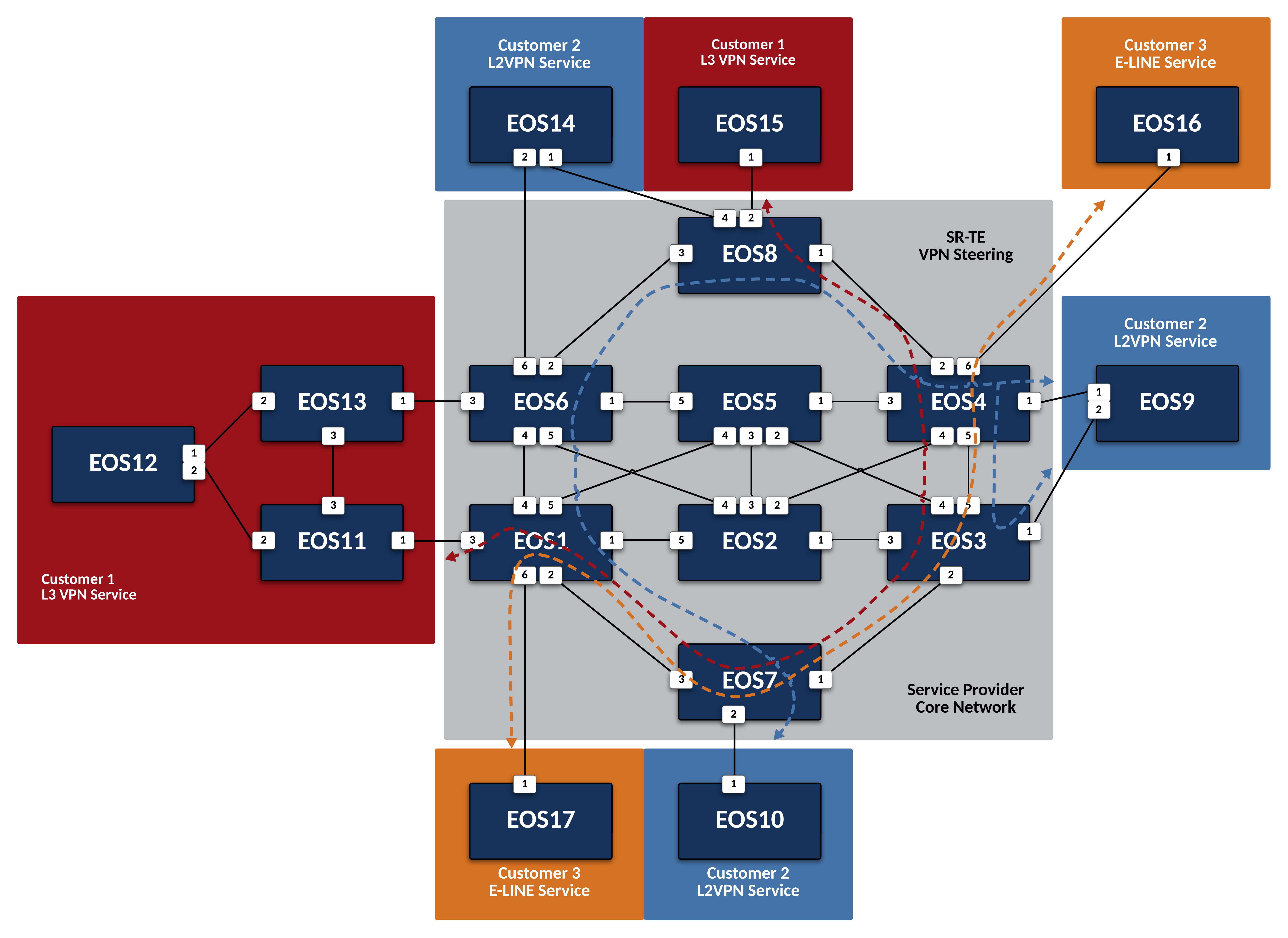
Leverage SR-TE to Steer VPN Traffic
Steer Customer 1 Layer 3 VPN Traffic
-
Use Segment Routing Traffic Engineering (SRTE) to manipulate L3VPN traffic for Customer-1. Configure the Service Provider network so that traffic from
EOS15toEOS12follows the path pictured above.- Use a BGP Color Community value of 12.
- The Binding SID for the TE policy should be 1000X12 (X = destination Node-ID)
- Only traffic for
EOS12’s Loopback should be matched. - Traffic should still be ECMP load balanced between PEs
EOS1andEOS6.
Steer Customer 2 Layer 2 VPN Traffic
-
Use SR-TE to manipulate L2VPN traffic for Customer-2. Configure the Service Provider network so that traffic from
EOS9toEOS10follows the path pictured above.- Use a BGP Color Community value of 10.
- The Binding SID for the TE policy should be 1000X12 (X = destination Node-ID)
- Only L2 traffic for
EOS10should be matched. - Traffic ingressing on
EOS3orEOS4should be sent via the pictured path.
Steer Customer 3 E-LINE Traffic
-
Use SR-TE to manipulate VPWS traffic for Customer-3. Configure the Service Provider network so that traffic between
EOS16andEOS17follows the path pictured above.- Use a BGP Color Community value of 1617.
- The Binding SID for the TE policy should be 1001617 (X = destination Node-ID)
- Only VPWS traffic for
EOS16andEOS17should be matched. - Traffic should follow the pictured path bidirectionally.
Limitation
Due to a limitation in software forwarding in vEOS-lab, forwarding of VPWS traffic into SR-TE tunnels does not function and as such, we cannot verify functionality via ICMP, etc. All control-plane functions should be verified using the commands above. Steering of VPWS traffic in hardware platforms functions as expected.
Success
Lab Complete!
