Campus Layer 3 Leaf-Spine with EVPN VXLAN
Preparing The Lab
- Baseline your lab environment:
- Click on
Console Accesson the top left of your lab menu. - Type
l3ls-evpnand hit enter at the prompt. - The script will pre-configure the topology with the exception of
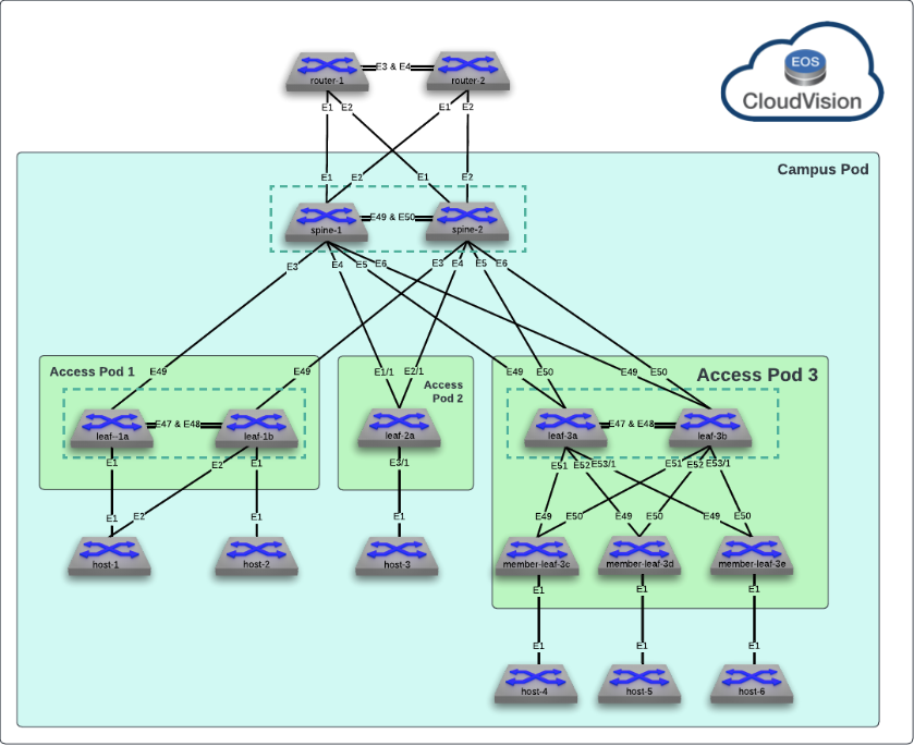
leaf-3aandmember-leaf-3e. These will be configured manually, via the CLI. See the CloudVision Studios Labs to see how to use CloudVision's guided Campus Workflows to configure the same topology via the UI.
- Click on
Lab Tasks
-
Most of the campus network has been pre-configured to save time. We will be focusing on Access Pod 3 which will be a Leaf-Spine Stack of 5 switches. The first step is to configure the secondary leaf,
leaf-3b. It's peer,leaf-3ahas already been configured. The first step is to establish the MLAG relationship with it. Configure the MLAG Vlan, SVI, Peer-link and Domain.Note
Arista EOS utilizes an Industry-Standard CLI. When entering configuration commands, be sure to first type
configureto enter configuration mode.-
Create the MLAG VLAN and SVI on
leaf-3b:Commands
vlan 4094
   name MLAG_PEER
   trunk group MLAG
!
no spanning-tree vlan-id 4094
!
interface Vlan4094
   description MLAG_PEER
   no autostate
   ip address 10.255.255.11/31
Note
We disable STP on the MLAG VLAN to prevent any delay in forwarding between the peers. Then, to prevent accidental loops, we use a trunk group to limit forwarding of the MLAG VLAN to interfaces with that are members of the trunk group as we will see later. In addition, note that the network used for the MLAG peering can be unique per pair or be reused across the infrastructure based on the operator's preference.
-
Configure the MLAG Peer Port-Channel and member links on
leaf-3b:Commands
interface Port-Channel47
   description MLAG_PEER_leaf-3a_Po47
   switchport mode trunk
   switchport trunk group MLAG
!
interface Ethernet47
   description MLAG_PEER_leaf-3a_Ethernet47
   channel-group 47 mode active
!
interface Ethernet48
   description MLAG_PEER_leaf-3a_Ethernet48
   channel-group 47 mode active
Note
The MLAG peer-link should be an unpruned trunk of all VLANs between the switches to ensure L2 consistency as they will be acting as a single STP bridge.
-
Create the MLAG Domain on
leaf-3bto establish the peering:Command
mlag configuration
   domain-id Access_Pod3_AGG
   local-interface Vlan4094
   peer-address 10.255.255.10
   peer-link Port-Channel47
   reload-delay mlag 300
   reload-delay non-mlag 330
Note
The
domain-idused for MLAG is locally significant between the peers and can be reused across different Access Pods. We have used a unique name for clarity in the lab. Thereload-delayoptions are set per best practices but can be tuned with the help of an Arista SE. -
Validate the configuration on
leaf-3bwith the following commands:Command
Expected Output
leaf-3b(config-mlag)#show port-channel dense

                   Flags
--------------------------- -------------------------------- -------------------------
   a - LACP Active             p - LACP Passive              * - static fallback
   F - Fallback enabled        f - Fallback configured       ^ - individual fallback
   U - In Use                  D - Down
   + - In-Sync                 - - Out-of-Sync               i - incompatible with agg
   P - bundled in Po           s - suspended                 G - Aggregable
   I - Individual              S - ShortTimeout              w - wait for agg
   C - Transmit disabled       M - Exceeds maximum weight
  E - Inactive. The number of configured port channels exceeds the config limit

Number of channels in use: 1
Number of aggregators: 1

   Port-Channel       Protocol    Ports
------------------ -------------- --------------------
   Po47(U)            LACP(a)     Et47(PG+) Et48(PG+)
Command
Expected Output
leaf-3b(config-mlag)#show mlag
MLAG Configuration:
domain-id                          :     Access_Pod3_AGG
local-interface                    :            Vlan4094
peer-address                       :       10.255.255.10
peer-link                          :      Port-Channel47
hb-peer-address                    :             0.0.0.0
peer-config                        :        inconsistent

MLAG Status:
state                              :              Active
negotiation status                 :           Connected
peer-link status                   :                  Up
local-int status                   :                  Up
system-id                          :   02:1c:73:b7:c6:01
dual-primary detection             :            Disabled
dual-primary interface errdisabled :               False

MLAG Ports:
Disabled                           :                   0
Configured                         :                   0
Inactive                           :                   0
Active-partial                     :                   0
Active-full                        :                   0
Note
Since our configuration is not complete, it is expected to be in an inconsistent state.
-
-
Configure the Layer 3 interfaces and BGP for the Underlay on the
leaf-3bswitch using the following criteria.-
Based on the diagram, configure L3 interfaces to
spine-1andspine-2. Also configure interface Loopback0 for use as the BGP Router ID:Commands
-
In addition, configure a L3 network to
leaf-3a:Commands
vlan 4093
   name LEAF_PEER_L3
   trunk group LEAF_PEER_L3
!
no spanning-tree vlan-id 4093
!
interface Port-Channel47
   switchport trunk group LEAF_PEER_L3
!
interface Vlan4093
   description MLAG_PEER_L3_PEERING
   ip address 10.255.2.11/31
Commands
Commands
leaf-3b(config-if-Vl4093)#show ip interface brief
                                                                                 Address
Interface         IP Address             Status       Protocol            MTU    Owner
----------------- ---------------------- ------------ -------------- ----------- -------
Ethernet49        10.0.0.25/31           up           up                 1500
Ethernet50        10.0.0.27/31           up           up                 1500
Loopback0         10.255.0.9/32          up           up                65535
Management0       192.168.0.18/24        up           up                 1500
Vlan4093          10.255.2.11/31         up           up                 1500
Vlan4094          10.255.255.11/31       up           up                 1500
Note
It is best practice to leverage a dedicated L3 network for BGP peering between the MLAG peers. For illustrative purposes, we have created a unique trunk group and added this L3 Vlan and the MLAG peer-link to it to ensure the VLAN is only allowed between the two MLAG peers.
-
Configure routing policies that will be leveraged with BGP on
leaf-3b:Note
These policies will ensure only intended networks are redistributed and routed via BGP per best practices.
Commands
ip prefix-list PL-L2LEAF-INBAND-MGMT seq 10 permit 10.10.10.0/24 ! ip prefix-list PL-LOOPBACKS-EVPN-OVERLAY seq 10 permit 10.255.0.0/24 eq 32 seq 20 permit 10.255.1.0/24 eq 32 ! route-map RM-CONN-2-BGP permit 10 match ip address prefix-list PL-LOOPBACKS-EVPN-OVERLAY ! route-map RM-CONN-2-BGP permit 20 match ip address prefix-list PL-L2LEAF-INBAND-MGMT ! route-map RM-MLAG-PEER-IN permit 10 description Make routes learned over MLAG Peer-link less preferred on spines to ensure optimal routing set origin incomplete -
Enable BGP and configure the neighbor relationships on
leaf-3b. Configure eBGP tospine-1andspine-2and iBGP toleaf-3a:Note
We set various best practice configurations like ECMP and disabling automation IPv4 AF peerings to ensure consistency in our lab. In addition, we are using a peer group to configure the neighbor attributes for the spines. This allows us to apply all BGP attributes within a group to each neighbor that is a member in a scalable method.
Commands
router bgp 65113
   router-id 10.255.0.9
   maximum-paths 4 ecmp 4
   no bgp default ipv4-unicast
   neighbor IPv4-UNDERLAY-PEERS peer group
   neighbor IPv4-UNDERLAY-PEERS send-community
   neighbor IPv4-UNDERLAY-PEERS maximum-routes 12000
   neighbor MLAG-IPv4-UNDERLAY-PEER peer group
   neighbor MLAG-IPv4-UNDERLAY-PEER remote-as 65113
   neighbor MLAG-IPv4-UNDERLAY-PEER next-hop-self
   neighbor MLAG-IPv4-UNDERLAY-PEER description leaf-3a
   neighbor MLAG-IPv4-UNDERLAY-PEER send-community
   neighbor MLAG-IPv4-UNDERLAY-PEER maximum-routes 12000
   neighbor MLAG-IPv4-UNDERLAY-PEER route-map RM-MLAG-PEER-IN in
   neighbor 10.0.0.24 peer group IPv4-UNDERLAY-PEERS
   neighbor 10.0.0.24 remote-as 65001
   neighbor 10.0.0.24 description spine-1_Ethernet6
   neighbor 10.0.0.26 peer group IPv4-UNDERLAY-PEERS
   neighbor 10.0.0.26 remote-as 65001
   neighbor 10.0.0.26 description spine-2_Ethernet6
   neighbor 10.255.2.10 peer group MLAG-IPv4-UNDERLAY-PEER
   neighbor 10.255.2.10 description leaf-3a
   redistribute connected route-map RM-CONN-2-BGP
   !
   address-family ipv4
      neighbor IPv4-UNDERLAY-PEERS activate
      neighbor MLAG-IPv4-UNDERLAY-PEER activate
Info
Since neighbor
10.255.2.10 remote-as 65113specifies an iBGP peering relationship (because the ASN is the same as this switch 65113), the receiving switch may not have a route to networks more than 1 hop away, hence the switches should each advertise that they are the next hop via thenext-hop-selfstatement applied to the peer group. While this scenario is only 2 iBGP peers, in a network fabric with several iBGP peers, a switch inside an AS (and not on an edge) may not have a route to a switch in any external AS. -
Validate the BGP configuration using the
show activecommand while in the “Router BGP” configuration section of the CLI (you'll have to exit one level). Also, check to see that BGP neighbors are establishedCommand
Expected Output
leaf-3b(config-router-bgp-af)#exit
leaf-3b(config-router-bgp)#show active
router bgp 65113
   router-id 10.255.0.9
   no bgp default ipv4-unicast
   maximum-paths 4 ecmp 4
   neighbor IPv4-UNDERLAY-PEERS peer group
   neighbor IPv4-UNDERLAY-PEERS send-community
   neighbor IPv4-UNDERLAY-PEERS maximum-routes 12000
   neighbor MLAG-IPv4-UNDERLAY-PEER peer group
   neighbor MLAG-IPv4-UNDERLAY-PEER remote-as 65113
   neighbor MLAG-IPv4-UNDERLAY-PEER next-hop-self
   neighbor MLAG-IPv4-UNDERLAY-PEER description leaf-3a
   neighbor MLAG-IPv4-UNDERLAY-PEER route-map RM-MLAG-PEER-IN in
   neighbor MLAG-IPv4-UNDERLAY-PEER send-community
   neighbor MLAG-IPv4-UNDERLAY-PEER maximum-routes 12000
   neighbor 10.0.0.24 peer group IPv4-UNDERLAY-PEERS
   neighbor 10.0.0.24 remote-as 65001
   neighbor 10.0.0.24 description spine-1_Ethernet6
   neighbor 10.0.0.26 peer group IPv4-UNDERLAY-PEERS
   neighbor 10.0.0.26 remote-as 65001
   neighbor 10.0.0.26 description spine-2_Ethernet6
   neighbor 10.255.2.10 peer group MLAG-IPv4-UNDERLAY-PEER
   neighbor 10.255.2.10 description leaf-3a
   redistribute connected route-map RM-CONN-2-BGP
   !
   address-family ipv4
      neighbor IPv4-UNDERLAY-PEERS activate
      neighbor MLAG-IPv4-UNDERLAY-PEER activate
Command
Expected Output
leaf-3b(config-router-bgp)#show ip bgp summary
BGP summary information for VRF default
Router identifier 10.255.0.9, local AS number 65113
Neighbor Status Codes: m - Under maintenance
  Description              Neighbor    V AS           MsgRcvd   MsgSent  InQ OutQ  Up/Down State   PfxRcd PfxAcc PfxAdv
  spine-1_Ethernet6        10.0.0.24   4 65001             11        14    0    0 00:00:49 Estab   15     15     7
  spine-2_Ethernet6        10.0.0.26   4 65001             13        14    0    0 00:00:49 Estab   15     15     17
  leaf-3a                  10.255.2.10 4 65113             10        12    0    0 00:00:48 Estab   19     19     17
-
-
With our Underlay routing set up, we can now configure the overlay network on
leaf-3bto advertise the user subnets to the rest of the site.-
Create a Loopback and VXLAN interface which will comprise our VTEP on
leaf-3b:Commands
interface Loopback1
   description VTEP_VXLAN_Tunnel_Source
   no shutdown
   ip address 10.255.1.8/32
!
interface Vxlan1
   description leaf-3b_VTEP
   vxlan source-interface Loopback1
   vxlan virtual-router encapsulation mac-address mlag-system-id
   vxlan udp-port 4789
Info
Since we are forming a redundant relationship with
leaf-3a, our MLAG peer, we used a shared VTEP IP. This allows both VTEPs to send and receive VXLAN traffic actively. -
Enable the EVPN Control-Plane peering in BGP towards the spines:
Commands
router bfd
   multihop interval 300 min-rx 300 multiplier 3
!
router bgp 65113
   neighbor EVPN-OVERLAY-PEERS peer group
   neighbor EVPN-OVERLAY-PEERS update-source Loopback0
   neighbor EVPN-OVERLAY-PEERS bfd
   neighbor EVPN-OVERLAY-PEERS ebgp-multihop 3
   neighbor EVPN-OVERLAY-PEERS send-community
   neighbor EVPN-OVERLAY-PEERS maximum-routes 0
   neighbor 172.16.1.1 peer group EVPN-OVERLAY-PEERS
   neighbor 172.16.1.1 remote-as 65001
   neighbor 172.16.1.1 description spine-1
   neighbor 172.16.1.2 peer group EVPN-OVERLAY-PEERS
   neighbor 172.16.1.2 remote-as 65001
   neighbor 172.16.1.2 description spine-2
   !
   address-family evpn
      neighbor EVPN-OVERLAY-PEERS activate
Info
We leverage eBGP Multihop over our Loopback0 interfaces for our EVPN peerings to ensure control-plane independence from the Underlay peering networks. In addition, BFD ensures quick reaction to changes in the underlay reachability.
-
With the configuration in place, verify the EVPN peerings are established on
leaf-3b:Command
Expected Output
leaf-3b(config-router-bgp-af)#show bgp evpn summary
BGP summary information for VRF default
Router identifier 10.255.0.9, local AS number 65113
Neighbor Status Codes: m - Under maintenance
  Description              Neighbor   V AS           MsgRcvd   MsgSent  InQ OutQ  Up/Down State   PfxRcd PfxAcc PfxAdv
  spine-1                  172.16.1.1 4 65001             24         4    0    0 00:00:23 Estab   27     27     0
  spine-2                  172.16.1.2 4 65001             24        16    0    0 00:00:22 Estab   27     27     27
-
-
Now that our overlay control-plane is in place, we can start to deploy our Layer 2 and Layer 3 Services to
leaf-3bfor client connectivity.-
Create the L2 VLANs used for client and management networks on
leaf-3b:Commands
-
Create the VLAN to VNI mappings on
leaf-3b:Commands
interface Vxlan1
   vxlan vlan 310 vni 10310
   vxlan vlan 320 vni 10320
   vxlan vlan 330 vni 10330
   vxlan vlan 410 vni 10410
Info
We map each VLAN locally to a global VNI. It is common to use an offset. In this case, we add 10,000 to the VLAN ID.
-
Create the VLAN as part of the BGP Control-Plane to signal the rest of the fabric on
leaf-3b:Commands
router bgp 65113
   !
   vlan 310
      rd 10.255.0.9:10310
      route-target both 10310:10310
      redistribute learned
   !
   vlan 320
      rd 10.255.0.9:10320
      route-target both 10320:10320
      redistribute learned
   !
   vlan 330
      rd 10.255.0.9:10330
      route-target both 10330:10330
      redistribute learned
   !
   vlan 410
      rd 10.255.0.9:10410
      route-target both 10410:10410
      redistribute learned
Info
With EVPN, we define each VLAN, or MAC VRF, as part of the BGP configuration. Each VLAN has a route distinguisher, or
rddefined to uniquely identify each router's advertisements. We use a sharedroute-targetto allow the various VTEPs to import and export routes advertised. Commonly this value is identical on all leaves. Lastly, we redistribute all locally learned MACs into BGP to allow other VTEPs to see what MACs are locally connected here. -
With the Layer 2 services in place, we can add the Layer 3 portion of the service to allow for routed traffic. Define a VRF and SVIs on
leaf-3bfor the configured VLANs:Commands
vrf instance campus
!
ip routing vrf campus
!
ip dhcp relay information option
!
interface Vlan10
   description Inband Management
   ip address 10.10.10.3/24
   ip virtual-router address 10.10.10.1
!
interface Vlan310
   description Access_Pod3-Data
   vrf campus
   ip address virtual 10.3.10.1/24
   ip helper-address 10.100.0.0 vrf default source-interface Loopback0
!
interface Vlan320
   description Access_Pod3-Voice
   vrf campus
   ip address virtual 10.3.20.1/24
   ip helper-address 10.100.0.0 vrf default source-interface Loopback0
!
interface Vlan330
   description Access_Pod3-Guest
   vrf campus
   ip address virtual 10.3.30.1/24
   ip helper-address 10.100.0.0 vrf default source-interface Loopback0
!
interface Vlan410
   description Access_Shared-IoT
   vrf campus
   ip address virtual 10.4.10.1/24
   ip helper-address 10.100.0.0 vrf default source-interface Loopback0
!
ip virtual-router mac-address 00:1c:73:00:00:99
Note
In a standard EVPN setup, we typically put all user networks in one or more VRFs. While they can live in the default VRF, it's not a recommended practice in most cases. The exception here is VLAN 10 which we are modeling for in-band management of the downstream member leaves. This network is not part of the overlay.
Info
VXLAN leverages Anycast gateways, which allows all VTEPs to simultaneously act as the default gateway. These use a shared virtual MAC instead of each switch's system MAC. Also note that we can redirect DHCP requests but since each VTEP shares the gateway IP, we use a Loopback address to source the DHCP relay to ensure it returns to the proper device.
-
Finally, configured the VXLAN mapping and EVPN settings for the VRF on
leaf-3b:Commands
interface Vxlan1
   vxlan vrf campus vni 5001
!
router bgp 65113
   !
   vrf campus
      rd 10.255.0.9:5001
      route-target import evpn 5001:5001
      route-target export evpn 5001:5001
      redistribute connected
Info
Each VRF is mapped to a VNI to allow for routing between VTEPs inside the VRF (inter-VLAN routing). Similar to the MAC VRF, the IP VRF in EVPN assigns an
rdandroute-targetvalue. -
With the configuration in place, verify the EVPN routes are being received on
leaf-3b:Command
Expected Output
leaf-3b(config-router-bgp-vrf-campus)#show bgp evpn
BGP routing table information for VRF default
Router identifier 10.255.0.9, local AS number 65113
Route status codes: * - valid, > - active, S - Stale, E - ECMP head, e - ECMP
                    c - Contributing to ECMP, % - Pending best path selection
Origin codes: i - IGP, e - EGP, ? - incomplete
AS Path Attributes: Or-ID - Originator ID, C-LST - Cluster List, LL Nexthop - Link Local Nexthop

          Network                Next Hop              Metric  LocPref Weight  Path
 * >Ec    RD: 10.255.0.7:10210 mac-ip 1638.914c.dc34
                                 10.255.1.7            -       100     0       65001 65112 i
 *  ec    RD: 10.255.0.7:10210 mac-ip 1638.914c.dc34
                                 10.255.1.7            -       100     0       65001 65112 i
 * >      RD: 10.255.0.9:10320 mac-ip 1e61.b0b0.38ba
                                 -                     -       -       0       i
 * >      RD: 10.255.0.9:10310 mac-ip ca6d.3c68.50f0
                                 -                     -       -       0       i
 * >Ec    RD: 10.255.0.5:10410 mac-ip d280.6ac0.9cc6
                                 10.255.1.5            -       100     0       65001 65111 i
 *  ec    RD: 10.255.0.5:10410 mac-ip d280.6ac0.9cc6
                                 10.255.1.5            -       100     0       65001 65111 i
 * >Ec    RD: 10.255.0.6:10410 mac-ip d280.6ac0.9cc6
                                 10.255.1.5            -       100     0       65001 65111 i
 *  ec    RD: 10.255.0.6:10410 mac-ip d280.6ac0.9cc6
!!!!!!!
< Output Truncated for Length>
Command
Expected Output
leaf-3b(config-router-bgp-vrf-campus)#show interface Vxlan1
Vxlan1 is up, line protocol is up (connected)
  Hardware is Vxlan
  Description: leaf-3b_VTEP
  Source interface is Loopback1 and is active with 10.255.1.8
  Listening on UDP port 4789
  Replication/Flood Mode is headend with Flood List Source: EVPN
  Remote MAC learning via EVPN
  VNI mapping to VLANs
  Static VLAN to VNI mapping is
    [310, 10310]      [320, 10320]      [330, 10330]      [410, 10410]

  Dynamic VLAN to VNI mapping for 'evpn' is
    [4098, 5001]
  Note: All Dynamic VLANs used by VCS are internal VLANs.
        Use 'show vxlan vni' for details.
  Static VRF to VNI mapping is
   [campus, 5001]
  Headend replication flood vtep list is:
   410 10.255.1.5      10.255.1.7
  MLAG Shared Router MAC is 021c.73b7.c601
-
-
Lastly, with the services in place on
leaf-3b, we can add the networks and connections to the downstream member leaves in the Pod.-
Create the Port-Channels and configure the interfaces towards the member leaves on
leaf-3b:Commands
interface Port-Channel51 description MEMBER-LEAF-3C_Po49 switchport trunk allowed vlan 10,310,320,330,410 switchport mode trunk mlag 51 ! interface Port-Channel52 description MEMBER-LEAF-3D_Po49 switchport trunk allowed vlan 10,310,320,330,410 switchport mode trunk mlag 52 ! interface Port-Channel531 description MEMBER-LEAF-3E_Po49 switchport trunk allowed vlan 10,310,320,330,410 switchport mode trunk mlag 531 ! interface Ethernet51 description MEMBER-LEAF-3C_Ethernet50 channel-group 51 mode active ! interface Ethernet52 description MEMBER-LEAF-3D_Ethernet50 channel-group 52 mode active ! interface Ethernet53/1 description MEMBER-LEAF-3E_Ethernet50 channel-group 531 mode active -
member-leaf-3ealso has only a base configuration. Since this is a member-leaf in the pod, it will only require configuration for the user VLANs and L2 links to the main closet leafs. Onmember-leaf-3econfigure the following:Commands
vlan 10
   name INBAND_MGMT
!
vlan 310
   name Access_Pod3-Data
!
vlan 320
   name Access_Pod3-Voice
!
vlan 330
   name Access_Pod3-Guest
!
vlan 410
   name Access_Shared-IoT
!
interface Port-Channel49
   description Access_Pod3_AGG_Po531
   no shutdown
   switchport
   switchport trunk allowed vlan 10,310,320,330,410
   switchport mode trunk
!
interface Ethernet1
   description Access_Pod3 Standard Port
   switchport access vlan 410
!
interface Ethernet49
   description LEAF-3A_Ethernet53/1
   no shutdown
   channel-group 49 mode active
!
interface Ethernet50
   description LEAF-3B_Ethernet53/1
   no shutdown
   channel-group 49 mode active
!
interface Vlan10
   description Inband Management
   no shutdown
   mtu 1500
   ip address 10.10.10.13/24
Info
Member Leaves require no EVPN or Layer 3 Configurations in a standard Cognitive Campus deployment.
-
With the configuration in place, verify connections between the leaves and members leaves. On
leaf-3b:Command
Expected Output
leaf-3b#show port-channel dense

                   Flags
--------------------------- -------------------------------- -------------------------
   a - LACP Active             p - LACP Passive              * - static fallback
   F - Fallback enabled        f - Fallback configured       ^ - individual fallback
   U - In Use                  D - Down
   + - In-Sync                 - - Out-of-Sync               i - incompatible with agg
   P - bundled in Po           s - suspended                 G - Aggregable
   I - Individual              S - ShortTimeout              w - wait for agg
   C - Transmit disabled       M - Exceeds maximum weight
  E - Inactive. The number of configured port channels exceeds the config limit

Number of channels in use: 4
Number of aggregators: 4

   Port-Channel       Protocol    Ports
------------------ -------------- -----------------------
   Po47(U)            LACP(a)     Et47(PG+) Et48(PG+)
   Po51(U)            LACP(a)     Et51(PG+) PEt51(P)
   Po52(U)            LACP(a)     Et52(PG+) PEt52(P)
   Po531(U)           LACP(a)     Et53/1(PG+) PEt53/1(P)
Command
Expected Output
leaf-3b#show mlag interfaces
                                                                                local/remote
   mlag       desc                            state       local       remote          status
---------- ------------------------- ----------------- ----------- ------------ ------------
     51       MEMBER-LEAF-3C_Po49       active-full        Po51         Po51           up/up
     52       MEMBER-LEAF-3D_Po49       active-full        Po52         Po52           up/up
    531       MEMBER-LEAF-3E_Po49       active-full       Po531        Po531           up/up
Command
Expected Output
leaf-3b#show interfaces trunk
Port            Mode            Status          Native vlan
Po47            trunk           trunking        1
Po51            trunk           trunking        1
Po52            trunk           trunking        1
Po531           trunk           trunking        1

Port            Vlans allowed
Po47            All
Po51            10,310,320,330,410
Po52            10,310,320,330,410
Po531           10,310,320,330,410

Port            Vlans allowed and active in management domain
Po47            1,10,310,320,330,410,4093-4094
Po51            10,310,320,330,410
Po52            10,310,320,330,410
Po531           10,310,320,330,410

Port            Vlans in spanning tree forwarding state
Po47            1,10,310,320,330,410,4093-4094
Po51            10,310,320,330,410
Po52            10,310,320,330,410
Po531           10,310,320,330,410
-
Test Client Connectivity
-
Validate bridged connectivity from
host-2tohost-6.-
Since the hosts are using DHCP on interface Ethernet1, run the show ip interface brief command on
host-6to find its IP address:Command
Expected Output
host-6#show ip int brief
                                                                               Address
Interface         IP Address            Status       Protocol           MTU    Owner
----------------- --------------------- ------------ -------------- ---------- -------
Ethernet1         10.4.10.11/24         up           up                1500
Management0       192.168.0.27/24       up           up                1500
Note
Since the IP address is assigned via DHCP, your device may have a different IP than what's shown above.
-
Ping and traceroute
host-6’s IP address from the CLI ofhost-2:Commands
Expected Output
host-2#ping 10.4.10.11 PING 10.4.10.11 (10.4.10.11) 72(100) bytes of data. 80 bytes from 10.4.10.11: icmp_seq=1 ttl=64 time=5.52 ms 80 bytes from 10.4.10.11: icmp_seq=2 ttl=64 time=4.49 ms 80 bytes from 10.4.10.11: icmp_seq=3 ttl=64 time=4.58 ms 80 bytes from 10.4.10.11: icmp_seq=4 ttl=64 time=4.42 ms 80 bytes from 10.4.10.11: icmp_seq=5 ttl=64 time=4.00 ms --- 10.4.10.11 ping statistics --- 5 packets transmitted, 5 received, 0% packet loss, time 21ms rtt min/avg/max/mdev = 4.004/4.602/5.516/0.497 ms, ipg/ewma 5.257/5.032 msExpected Output
host-2#traceroute 10.4.10.11
traceroute to 10.4.10.11 (10.4.10.11), 30 hops max, 60 byte packets
 1  10.4.10.11 (10.4.10.11)  6.818 ms  8.581 ms  9.080 ms
Info
Since
host-2andhost-6are in the same L2 network, the hops across the spine (when the frame is encapsulated in VXLAN) are transparent. -
How did
host-2get tohost-6over the Layer 3 fabric? Let's check the EVPN control-plane first. Onleaf-1b, inspect the EVPN Control-Plane for the MAC or IP ofhost-6:Note
The MAC of
host-6may differ in your lab.Commands
Expected Output
leaf-1b#show bgp evpn route-type mac-ip 8ab3.a9d7.b4a4 detail
BGP routing table information for VRF default
Router identifier 10.255.0.6, local AS number 65111
BGP routing table entry for mac-ip 8ab3.a9d7.b4a4, Route Distinguisher: 10.255.0.8:10410
 Paths: 2 available
  65001 65113
    10.255.1.8 from 172.16.1.2 (172.16.1.2)
      Origin IGP, metric -, localpref 100, weight 0, tag 0, valid, external, ECMP head, ECMP, best, ECMP contributor
      Extended Community: Route-Target-AS:10410:10410 TunnelEncap:tunnelTypeVxlan
      VNI: 10410 ESI: 0000:0000:0000:0000:0000
  65001 65113
    10.255.1.8 from 172.16.1.1 (172.16.1.1)
      Origin IGP, metric -, localpref 100, weight 0, tag 0, valid, external, ECMP, ECMP contributor
      Extended Community: Route-Target-AS:10410:10410 TunnelEncap:tunnelTypeVxlan
      VNI: 10410 ESI: 0000:0000:0000:0000:0000
<Output Truncated for length>
Info
The MAC is learned via an EVPN Type 2 MAC Route. The detailed output above shows the originating routers
rdand theroute-targetconfigured. You will also see the tunnel type specified as VXLAN with the desired VNI and the next-hop address as the VTEP IP address. -
We know how
leaf-1blearned the MAC. Let's check to see how it was installed in the forwarding tables onleaf-1b:Commands
Expected Output
leaf-1b#show mac address-table address 8ab3.a9d7.b4a4
          Mac Address Table
------------------------------------------------------------------

Vlan    Mac Address       Type        Ports      Moves   Last Move
----    -----------       ----        -----      -----   ---------
 410    8ab3.a9d7.b4a4    DYNAMIC     Vx1        1       0:20:04 ago
Total Mac Addresses for this criterion: 1

          Multicast Mac Address Table
------------------------------------------------------------------

Vlan    Mac Address       Type        Ports
----    -----------       ----        -----
Total Mac Addresses for this criterion: 0
Commands
Expected Output
leaf-1b#show vxlan address-table address 8ab3.a9d7.b4a4 Vxlan Mac Address Table ---------------------------------------------------------------------- VLAN Mac Address Type Prt VTEP Moves Last Move ---- ----------- ---- --- ---- ----- --------- 410 8ab3.a9d7.b4a4 EVPN Vx1 10.255.1.8 1 0:20:58 ago Total Remote Mac Addresses for this criterion: 1 -
What about inter-VLAN routed traffic? Let's try to reach
host-6fromhost-3:Commands
Expected Output
host-3#ping 10.4.10.11 PING 10.4.10.11 (10.4.10.11) 72(100) bytes of data. 80 bytes from 10.4.10.11: icmp_seq=1 ttl=62 time=5.80 ms 80 bytes from 10.4.10.11: icmp_seq=2 ttl=62 time=4.82 ms 80 bytes from 10.4.10.11: icmp_seq=3 ttl=62 time=4.76 ms 80 bytes from 10.4.10.11: icmp_seq=4 ttl=62 time=4.72 ms 80 bytes from 10.4.10.11: icmp_seq=5 ttl=62 time=4.81 ms --- 10.4.10.11 ping statistics --- 5 packets transmitted, 5 received, 0% packet loss, time 23ms rtt min/avg/max/mdev = 4.722/4.979/5.796/0.409 ms, ipg/ewma 5.751/5.373 msExpected Output
host-3#traceroute 10.4.10.11
traceroute to 10.4.10.11 (10.4.10.11), 30 hops max, 60 byte packets
 1  * * *
 2  * * *
 3  10.4.10.11 (10.4.10.11)  13.359 ms  11.168 ms  14.336 ms
Info
Since
host-3andhost-6are in different L2 networks, the source host will use its default gateway which is an Anycast gateway on the first hop,leaf-2a.leaf-2awill route the traffic over the Layer 3 VNI (5001) to the destination leaf which will in turn route the traffic into the destination VLAN (410). This is called Symmetric IRB. The missing hops are expected in the traceroute as the Anycast gateway cannot properly source a reply from the shared address. There are operational tools and configurations in EOS to provide this functionality. Ask an Arista SE! -
Similarly, let's check how
leaf-2alearned wherehost-6was via the EVPN Control-Plane :Commands
Expected Output
leaf-2a#show bgp evpn route-type mac-ip 10.4.10.11 detail
BGP routing table information for VRF default
Router identifier 10.255.0.7, local AS number 65112
BGP routing table entry for mac-ip 8ab3.a9d7.b4a4 10.4.10.11, Route Distinguisher: 10.255.0.8:10410
 Paths: 2 available
  65001 65113
    10.255.1.8 from 172.16.1.1 (172.16.1.1)
      Origin IGP, metric -, localpref 100, weight 0, tag 0, valid, external, ECMP head, ECMP, best, ECMP contributor
      Extended Community: Route-Target-AS:5001:5001 Route-Target-AS:10410:10410 TunnelEncap:tunnelTypeVxlan EvpnRouterMac:02:1c:73:b7:c6:01
      VNI: 10410 L3 VNI: 5001 ESI: 0000:0000:0000:0000:0000
  65001 65113
    10.255.1.8 from 172.16.1.2 (172.16.1.2)
      Origin IGP, metric -, localpref 100, weight 0, tag 0, valid, external, ECMP, ECMP contributor
      Extended Community: Route-Target-AS:5001:5001 Route-Target-AS:10410:10410 TunnelEncap:tunnelTypeVxlan EvpnRouterMac:02:1c:73:b7:c6:01
      VNI: 10410 L3 VNI: 5001 ESI: 0000:0000:0000:0000:0000
BGP routing table entry for mac-ip 8ab3.a9d7.b4a4 10.4.10.11, Route Distinguisher: 10.255.0.9:10410
 Paths: 2 available
  65001 65113
    10.255.1.8 from 172.16.1.2 (172.16.1.2)
      Origin IGP, metric -, localpref 100, weight 0, tag 0, valid, external, ECMP head, ECMP, best, ECMP contributor
      Extended Community: Route-Target-AS:5001:5001 Route-Target-AS:10410:10410 TunnelEncap:tunnelTypeVxlan EvpnRouterMac:02:1c:73:b7:c6:01
      VNI: 10410 L3 VNI: 5001 ESI: 0000:0000:0000:0000:0000
  65001 65113
    10.255.1.8 from 172.16.1.1 (172.16.1.1)
      Origin IGP, metric -, localpref 100, weight 0, tag 0, valid, external, ECMP, ECMP contributor
      Extended Community: Route-Target-AS:5001:5001 Route-Target-AS:10410:10410 TunnelEncap:tunnelTypeVxlan EvpnRouterMac:02:1c:73:b7:c6:01
      VNI: 10410 L3 VNI: 5001 ESI: 0000:0000:0000:0000:0000
Info
The host route / ARP is learned via an EVPN Type 2 MAC-IP Route. The detailed output above shows the originating routers
rdand theroute-targetconfigured. You will also see the tunnel type specified as VXLAN with the desired VNI and the next-hop address as the VTEP IP address. -
We know how
leaf-2alearned the route. Let's check to see how it was installed in the forwarding tables onleaf-2a:Commands
Expected Output
leaf-2a#show ip route vrf campus 10.4.10.11

VRF: campus
Source Codes:
       C - connected, S - static, K - kernel,
       O - OSPF, O IA - OSPF inter area, O E1 - OSPF external type 1,
       O E2 - OSPF external type 2, O N1 - OSPF NSSA external type 1,
       O N2 - OSPF NSSA external type2, O3 - OSPFv3,
       O3 IA - OSPFv3 inter area, O3 E1 - OSPFv3 external type 1,
       O3 E2 - OSPFv3 external type 2,
       O3 N1 - OSPFv3 NSSA external type 1,
       O3 N2 - OSPFv3 NSSA external type2, B - Other BGP Routes,
       B I - iBGP, B E - eBGP, R - RIP, I L1 - IS-IS level 1,
       I L2 - IS-IS level 2, A B - BGP Aggregate,
       A O - OSPF Summary, NG - Nexthop Group Static Route,
       V - VXLAN Control Service, M - Martian,
       DH - DHCP client installed default route,
       DP - Dynamic Policy Route, L - VRF Leaked,
       G  - gRIBI, RC - Route Cache Route,
       CL - CBF Leaked Route

 B E      10.4.10.11/32 [200/0]
           via VTEP 10.255.1.8 VNI 5001 router-mac 02:1c:73:b7:c6:01 local-interface Vxlan1
-
Success
Lab Complete!