Arista CI Workshop - Campus Layer 2 Leaf Spine
This workshop will leverage open-source tools for the Day 0 configuration development, deployment, and documentation of the underlay infrastructure for our Campus topology. It then switches to configuring and managing the Day 2 operations of endpoint connectivity with CloudVision Studios by setting port profiles, and making use of the Quick Actions UI to assign quickly assign those profiles to ports.
This section will cover the following:
- Arista (Architect, Validate, Deploy) Ansible Collection
- Network Data Models
- Initial Deployment (Day 0 Provisioning)
- Ongoing Operations (Day 2 and Beyond)
- Validation and Troubleshooting
Each attendee will receive a dedicated virtual lab environment with Git, VS Code, and Ansible installed and ready to use.
Attendees will need the following:
- A laptop
- An account on GitHub
- Familiarity with the concepts and tools covered in the previous Automation Fundamentals workshop (Git, VS Code, Jinja/YAML, Ansible)
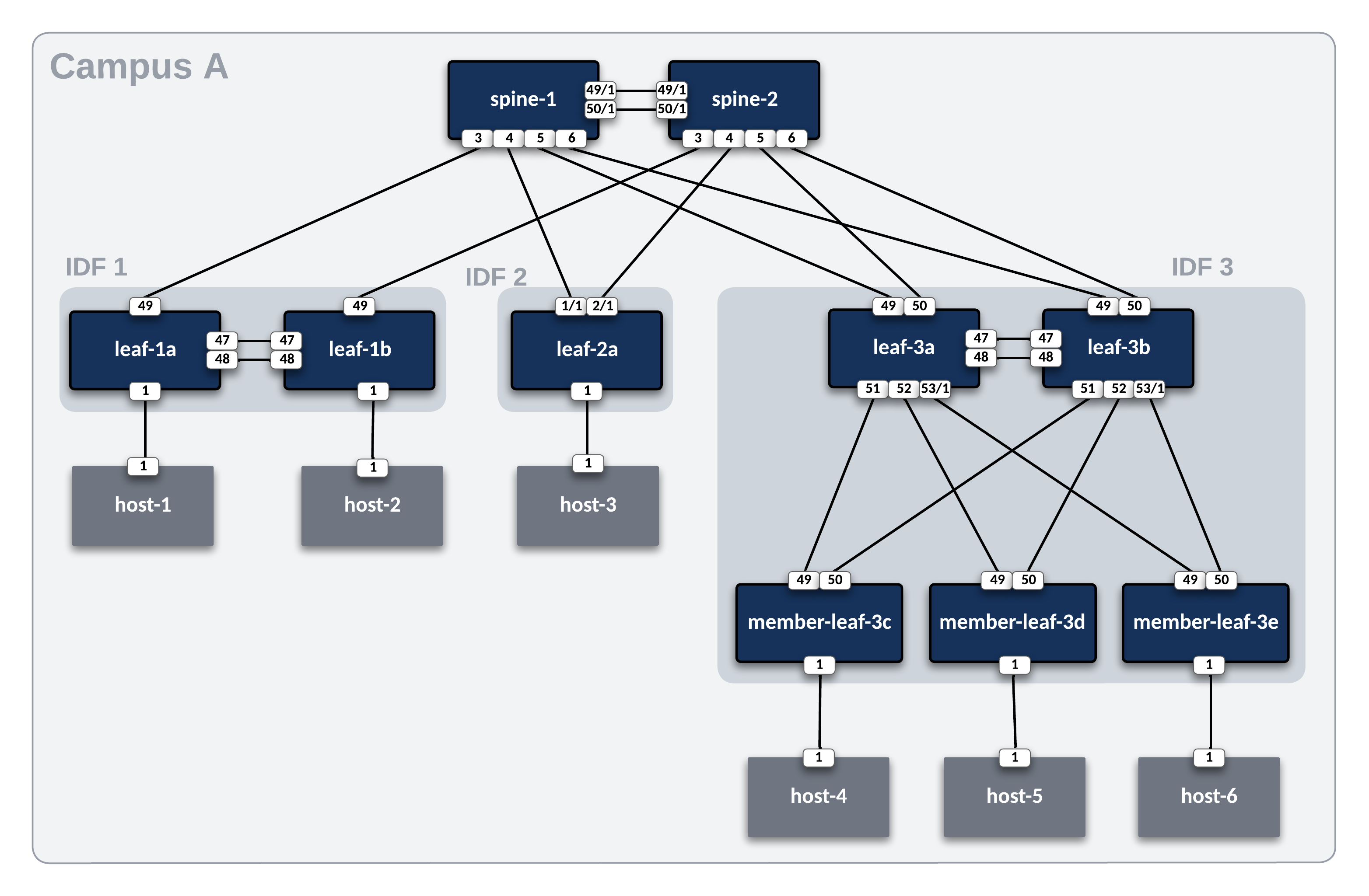
Lab Topology Overview
Throughout this section, we will use the following campus topology. Click on the image to zoom in for details.
Basic EOS Switch Configuration
Basic connectivity between the Ansible controller host and the switches must be established before Ansible can be used to deploy configurations. The following should be configured on all switches:
- Switch Hostname
- IP enabled interface
- Username and Password defined
- Management eAPI enabled
Info
In the ATD environment, cEOS virtual switches use Management0 in the default VRF. When using actual hardware or vEOS switches, Management1 is used. The included basic switch configurations may need to be adjusted for your environment.
Below is an example basic configuration file for spine-1:
!
no aaa root
!
username admin privilege 15 role network-admin secret sha512 $6$eucN5ngreuExDgwS$xnD7T8jO..GBDX0DUlp.hn.W7yW94xTjSanqgaQGBzPIhDAsyAl9N4oScHvOMvf07uVBFI4mKMxwdVEUVKgY/.
!
hostname spine-1
!
management api http-commands
   no shutdown
!
interface Management0
   ip address 192.168.0.10/24
!
ip routing
!
ip route vrf MGMT 0.0.0.0/0 192.168.0.1
!
Ansible Inventory
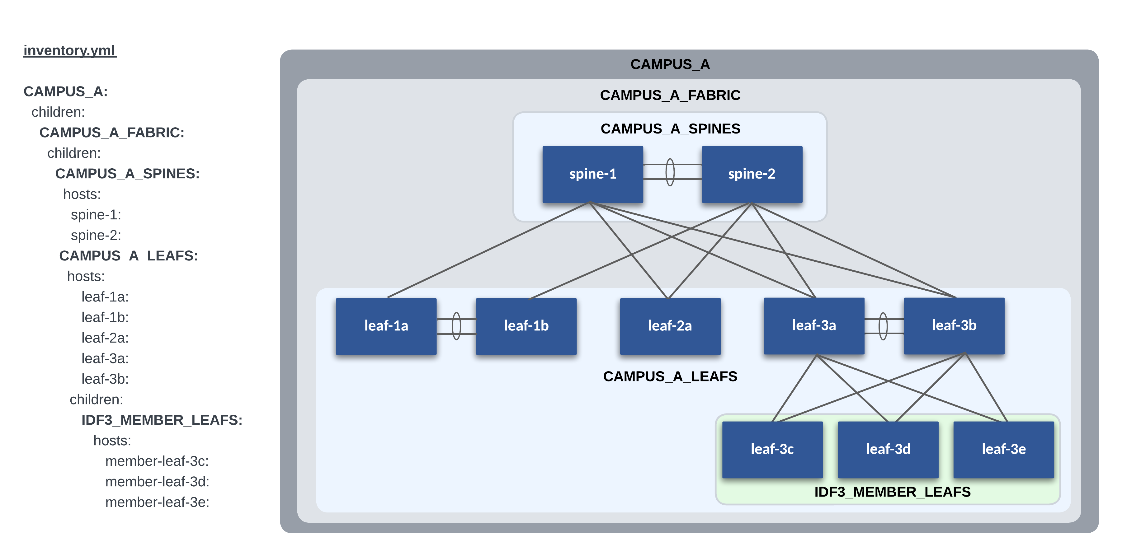
Our lab Campus L2LS topology contains one site, Campus A. Even though we only have one site in this workshop, we still follow our recommended practice of using the sites directory for future scalability.
The following is a graphical representation of the Ansible inventory groups and naming scheme used for Campus A in this example.
AVD Fabric Variables
To apply AVD variables to the nodes in the fabric, we make use of Ansible group_vars. How and where you define the variables is your choice. The group_vars table below is one example of AVD fabric variables for Campus A.
| group_vars/ | Description |
|---|---|
| CAMPUS_A_FABRIC.yml | Fabric, Topology, and Device settings |
| CAMPUS_A_SPINES.yml | Device type for Spines |
| CAMPUS_A_LEAFS.yml | Device type for Leafs |
| CAMPUS_A_NETWORK_SERVICES.yml | VLANs, VRFs, SVIs |
Each group_vars file is listed in the following tabs.
At the Fabric level (CAMPUS_A_FABRIC), the following variables are defined in group_vars/CAMPUS_A_FABRIC.yml. The fabric name, node type defaults, and interface links are defined at this level. Other variables you must supply include:
- spanning_tree_mode
- mlag_peer_ipv4_pool
The l3spine node will need these additional variables set.
- loopback_ipv4_pool
- mlag_peer_l3_ipv4_pool
- virtual_router_mac_address
Variables applied under the node key type (l3spine/l2leaf) defaults section are inherited by nodes under each type. These variables may be overwritten under the node itself.
The spine interface used by a particular leaf is defined from the leaf's perspective with a variable called uplink_switch_interfaces. For example, leaf-1a has a unique variable uplink_switch_interfaces: [Ethernet49] defined. This means that leaf-1a is connected to spine-1 Ethernet3.
---
fabric_name: CAMPUS_A_FABRIC

# Repeat MLAG addressing between pairs
fabric_ip_addressing:
  mlag:
    algorithm: same_subnet

# Generate CloudVision Tags based on AVD data
generate_cv_tags:
  topology_hints: true
  campus_fabric: true

# Used to generate CloudVision device tags with the `generate_cv_tags.campus_fabric` feature.
campus: Cleveland
campus_pod: Campus A

# Spine Switches
l3spine:
  defaults:
    platform: cEOS
    spanning_tree_mode: mstp
    loopback_ipv4_pool: 10.1.252.0/24
    mlag_peer_ipv4_pool: 10.1.253.0/31
    mlag_peer_l3_ipv4_pool: 10.1.253.2/31
    virtual_router_mac_address: 00:1c:73:00:dc:01
    mlag_interfaces: [ Ethernet49/1, Ethernet50/1 ]
  node_groups:
    - group: CAMPUS_A_SPINES
      nodes:
        - name: spine-1
          id: 1
          mgmt_ip: 192.168.0.12/24
        - name: spine-2
          id: 2
          mgmt_ip: 192.168.0.13/24

# Leaf Switches
l2leaf:
  defaults:
    platform: cEOS
    mlag_peer_ipv4_pool: 10.1.253.0/31
    spanning_tree_mode: mstp
    uplink_switches: [ spine-1, spine-2 ]
    uplink_interfaces: [ Ethernet49, Ethernet50 ]
    mlag_interfaces: [ Ethernet47, Ethernet48 ]
  node_groups:
    - group: IDF1
      filter:
        tags: [ "IDF1_DATA", "IDF1_VOICE" ]
      campus_access_pod: IDF1
      nodes:
        - name: leaf-1a
          id: 1
          mgmt_ip: 192.168.0.14/24
          uplink_interfaces: [ Ethernet49 ]
          uplink_switches: [ spine-1 ]
          uplink_switch_interfaces: [ Ethernet3 ]
        - name: leaf-1b
          id: 2
          mgmt_ip: 192.168.0.15/24
          uplink_interfaces: [ Ethernet49 ]
          uplink_switches: [ spine-2 ]
          uplink_switch_interfaces: [ Ethernet3 ]
    - group: IDF2
      filter:
        tags: [ "IDF2_DATA", "IDF2_VOICE" ]
      mlag: false
      nodes:
        - name: leaf-2a
          id: 3
          mgmt_ip: 192.168.0.16/24
          uplink_interfaces: [ Ethernet1/1, Ethernet2/1 ]
          uplink_switch_interfaces: [ Ethernet4, Ethernet4 ]
    - group: IDF3
      filter:
        tags: [ "IDF3_DATA", "IDF3_VOICE" ]
      campus_access_pod: IDF3
      nodes:
        - name: leaf-3a
          id: 4
          mgmt_ip: 192.168.0.17/24
          uplink_switch_interfaces: [ Ethernet5, Ethernet5 ]
        - name: leaf-3b
          id: 5
          mgmt_ip: 192.168.0.18/24
          uplink_switch_interfaces: [ Ethernet6, Ethernet6 ]
    - group: IDF3_3C
      filter:
        tags: [ "IDF3_DATA", "IDF3_VOICE" ]
      campus_access_pod: IDF3
      cv_tags_topology_type: member-leaf
      mlag: false
      nodes:
        - name: member-leaf-3c
          id: 6
          mgmt_ip: 192.168.0.19/24
          uplink_switches: [ leaf-3a, leaf-3b ]
          uplink_switch_interfaces: [ Ethernet51, Ethernet51 ]
    - group: IDF3_3D
      filter:
        tags: [ "IDF3_DATA", "IDF3_VOICE" ]
      campus_access_pod: IDF3
      cv_tags_topology_type: member-leaf
      mlag: false
      nodes:
        - name: member-leaf-3d
          id: 7
          mgmt_ip: 192.168.0.20/24
          uplink_switches: [ leaf-3a, leaf-3b ]
          uplink_switch_interfaces: [ Ethernet52, Ethernet52 ]
    - group: IDF3_3E
      filter:
        tags: [ "IDF3_DATA", "IDF3_VOICE" ]
      campus_access_pod: IDF3
      cv_tags_topology_type: member-leaf
      mlag: false
      nodes:
        - name: member-leaf-3e
          id: 8
          mgmt_ip: 192.168.0.21/24
          uplink_switches: [ leaf-3a, leaf-3b ]
          uplink_switch_interfaces: [ Ethernet53/1, Ethernet53/1 ]

##################################################################
# Underlay Routing Protocol - ran on Spines
##################################################################

underlay_routing_protocol: OSPF
In an L2LS design, there are two types of spine nodes: spine and l3spine. In AVD, the node type defines the functionality and the EOS CLI configuration to be generated. For our L2LS topology, we will use node type l3spine to include SVI functionality.
In an L2LS design, we have one type of leaf node: l2leaf. This will provide L2 functionality to the leaf nodes. Additionally, we will be setting the CloudVision tags we want to use for the Campus IDF view, and Quick Actions interface configuration. One thing you may notice that is different, and that is the value for the data_path: key in the generate_cv_tags: section. What this enables us to do is dynamically set the Access-Pod value based on the AVD configured MLAG domain id.
You add VLANs to the Fabric by updating the group_vars/CAMPUS_A_NETWORK_SERVICES.yml. Each VLAN will be given a name and a list of tags. The tags filter the VLAN to specific Leaf Pairs. These variables are applied to spine and leaf nodes since they are a part of this nested group.
---
tenants:
  - name: CAMPUS_A
    vrfs:
      - name: default
        svis:
          - id: 110
            name: 'IDF1_DATA'
            tags: [ "IDF1_DATA" ]
            enabled: true
            ip_virtual_router_addresses:
              - 10.1.10.1
            nodes:
              - node: spine-1
                ip_address: 10.1.10.2/24
              - node: spine-2
                ip_address: 10.1.10.3/24
          - id: 120
            name: 'IDF1_VOICE'
            tags: [ "IDF1_VOICE" ]
            enabled: true
            ip_virtual_router_addresses:
              - 10.1.20.1
            nodes:
              - node: spine-1
                ip_address: 10.1.20.2/24
              - node: spine-2
                ip_address: 10.1.20.3/24
          - id: 210
            name: 'IDF2_DATA'
            tags: [ "IDF2_DATA" ]
            enabled: true
            ip_virtual_router_addresses:
              - 10.2.10.1
            nodes:
              - node: spine-1
                ip_address: 10.2.10.2/24
              - node: spine-2
                ip_address: 10.2.10.3/24
          - id: 220
            name: 'IDF2_VOICE'
            tags: [ "IDF2_VOICE" ]
            enabled: true
            ip_virtual_router_addresses:
              - 10.2.20.1
            nodes:
              - node: spine-1
                ip_address: 10.2.20.2/24
              - node: spine-2
                ip_address: 10.2.20.3/24
Connected Endpoints
What about connected endpoints? If you have used AVD before, or attended one of the other AVD focused automation workshops, you may remember that we almost always configure the ports on the leafs that the host devices connect to via another yaml file with CONNECTED_ENDPOINTS in the name.
In this workshop we are showcasing the interoperability and co-existence of AVD generated configurations, and making quick configuration changes with CloudVision, and specifically, the Access Interface Quick Actions configuration area to quickly assign port-profiles to switch ports.
Global Variables
In a multi-site environment, some variables must be applied to all sites. They include AAA, Local Users, NTP, Syslog, DNS, and TerminAttr. Instead of updating these same variables in multiple inventory group_vars, we can use a single global variable file and import the variables at playbook runtime. This allows us to make a single change applied to all sites.
For example, in our lab, we use a global variable file global_vars/global_campus_vars.yml.
AVD provides a global_vars plugin that enables the use of global variables.
The global_vars plugin must be enabled in the ansible.cfg file as shown below:
#enable global vars
vars_plugins_enabled = arista.avd.global_vars, host_group_vars

#define global vars path
[vars_global_vars]
paths = ../../global_vars
Info
If a folder is used as in the example above, all files in the folder will be parsed in alphabetical order.
Example Global Vars File
global_vars/global_campus_vars.yml
---
# Credentials for EOS Switches
ansible_user: arista
ansible_password: "{{ lookup('env', 'LABPASSPHRASE') }}"
ansible_network_os: arista.eos.eos
# Configure privilege escalation
ansible_become: true
ansible_become_method: enable
# HTTPAPI configuration
ansible_connection: httpapi
ansible_httpapi_port: 443
ansible_httpapi_use_ssl: true
ansible_httpapi_validate_certs: false
ansible_python_interpreter: $(which python3)
avd_data_validation_mode: error

# arista.avd.cv_deploy role parameters
# Export token using 'export CV_TOKEN=<generated token here>'
cv_token: "{{ lookup('env', 'CV_TOKEN') }}"
cv_server: cvp
cv_verify_certs: false

# TerminAttr settings
cv_settings:
  onprem_clusters:
    - name: atd-cvp
      servers:
        - name: 192.168.0.5
  terminattr:
    disable_aaa: true

# AAA settings and local users
aaa_settings:
  authorization:
    exec:
      default: local
  local_users:
    - name: arista
      privilege: 15
      role: network-admin
      sha512_password: "{{ ansible_password | password_hash('sha512', salt='arista', rounds=5000) }}"
      ssh_key: "{{ lookup('ansible.builtin.file', '~/.ssh/id_rsa.pub') }}"

# DNS settings
dns_settings:
  domain: atd.lab
  servers:
    - ip_address: 192.168.0.1

# NTP Servers IP or DNS name, first NTP server will be preferred, and sourced from Management VRF
ntp_settings:
  servers:
    - name: 192.168.0.1
      iburst: true

# OOB Management network default gateway.
mgmt_gateway: 192.168.0.1
mgmt_interface_vrf: default
mgmt_interface: Management0

# Point to Point Links MTU Override for Lab
p2p_uplinks_mtu: 1500
Data Models
AVD provides a network-wide data model and is typically broken into multiple group_vars files to simplify and categorize variables with their respective functions. We break the data model into three categories: topology, services, and ports.
Fabric Topology
The physical fabric topology is defined by providing interface links between the spine and leaf nodes. The group_vars/CAMPUS_A_FABRIC.yml file defines this portion of the data model. In our lab, the spines provide layer 3 routing of SVIs and P2P links using a node type called l3spines. The leaf nodes are purely layer 2 and use the node type l2leaf. An AVD L2LS design typically uses two node type keys: l3spine and l2leaf. AVD Node Type documentation can be found here.
Spine and Leaf Nodes
The example data model below defines each site's spine and leaf nodes for each site. Refer to the inline comments for variable definitions. Under each node_type_key you have key/value pairs for defaults, node_groups, and nodes. Note that key/value pairs may be overwritten with the following descending order of precedence. The key/value closest to the node will be used.
- defaults
- node_groups
- nodes
# Spine Switches

# node_type_key for providing L3 services
l3spine:
  # default key/values for all l3spine nodes
  defaults:
    # Platform dependent default settings for mlag timers, tcam profiles, LANZ, management interface
    platform: cEOS
    # Spanning Tree
    spanning_tree_mode: mstp
    # Loopback0 pool, used in conjunction with value of `id:` under each node
    loopback_ipv4_pool: 10.1.252.0/24
    # IP Pool for MLAG peer link
    mlag_peer_ipv4_pool: 10.1.253.0/31
    # IP Pool for L3 peering over the MLAG peer link
    mlag_peer_l3_ipv4_pool: 10.1.253.2/31
    # Virtual MAC address used in vARP
    virtual_router_mac_address: 00:1c:73:00:dc:01
    # Default MLAG interfaces between spine nodes
    mlag_interfaces: [ Ethernet49/1, Ethernet50/1 ]
  # keyword for node groups, two nodes within a node group will form an MLAG pair
  node_groups:
    # User-defined node group name
    - group: CAMPUS_A_SPINES
      # key word for nodes
      nodes:
        - name: spine-1
          # unique identifier used for IP address calculations
          id: 1
          # Management address assigned to the defined management interface
          mgmt_ip: 192.168.0.12/24
        - name: spine-2
          id: 2
          mgmt_ip: 192.168.0.13/24

# Leaf Switches
l2leaf:
  defaults:
    platform: cEOS
    mlag_peer_ipv4_pool: 10.1.253.0/31
    spanning_tree_mode: mstp
    # Default uplink switches from leaf perspective
    uplink_switches: [ spine-1, spine-2 ]
    # Default uplink interfaces on leaf nodes connecting to the spines
    uplink_interfaces: [ Ethernet49, Ethernet50 ]
    # Default leaf MLAG interfaces
    mlag_interfaces: [ Ethernet47, Ethernet48 ]
  node_groups:
    # User-defined node group name
    - group: IDF1
      # Filter which Vlans will be applied to the node_group, comma-separated tags supported
      # Tags for each Vlan are defined in the CAMPUS_A_NETWORK_SERVICES.yml
      filter:
        tags: [ "IDF1_DATA", "IDF1_VOICE" ]
      # Name of the Campus access pod.
      campus_access_pod: IDF1
      nodes:
        - name: leaf-1a
          id: 1
          mgmt_ip: 192.168.0.14/24
          # Define which interface is configured on the uplink switch
          # In this example leaf-1a connects to spine-1 only
          # on the following port. This will be unique to each leaf
          uplink_interfaces: [ Ethernet49 ]
          uplink_switches: [ spine-1 ]
          uplink_switch_interfaces: [ Ethernet3 ]
        - name: s1-leaf2
          id: 2
          mgmt_ip: 192.168.0.15/24
          uplink_interfaces: [ Ethernet49 ]
          uplink_switches: [ spine-2 ]
          uplink_switch_interfaces: [ Ethernet3 ]
    - group: IDF2
      filter:
        tags: [ "IDF2_DATA", "IDF2_VOICE" ]
      mlag: false
      nodes:
        - name: leaf-2a
          id: 3
          mgmt_ip: 192.168.0.16/24
          uplink_interfaces: [ Ethernet1/1, Ethernet2/1 ]
          uplink_switch_interfaces: [ Ethernet4, Ethernet4 ]
    ...output abbreviated
Network Services
Network Services, such as VLANs, SVIs, and VRFs, are defined in this section. The following Campus A example defines VLANs and SVIs for multiple VLANs per IDF group in the default VRF. Additional VRF definitions can also be applied.
---
tenants:
  # User-defined Tenant/Fabric name
  - name: CAMPUS_A
    # key-word
    vrfs:
      # Default VRF
      - name: default
        # key-word
        svis:
          # Vlan ID
          - id: 110
            # Vlan Name
            name: 'IDF1_DATA'
            # Tag assigned to Vlan. Used as a filter by each node_group
            tags: [ "'IDF1_DATA'" ]
            enabled: true
            # SVI Virtual ARP address, used along with pre-defined virtual_router_mac_address
            ip_virtual_router_addresses:
              - 10.1.10.1
            # Which nodes to apply physical SVI address
            nodes:
              - node: spine-1
                ip_address: 10.1.10.2/24
              - node: spine-2
                ip_address: 10.1.10.3/24
          - id: 120
            name: 'IDF1_VOICE'
            tags: [ "IDF1_VOICE" ]
            enabled: true
            ip_virtual_router_addresses:
              - 10.1.20.1
            nodes:
              - node: spine-1
                ip_address: 10.1.20.2/24
              - node: spine-2
                ip_address: 10.1.20.3/24
          ...output abbreviated
The Playbooks
The two playbooks primarily used for this workshop are build.yml and cvp.yml. Expand the tabs below to reveal the content.
build.yml Playbook
---
- name: Build Switch configuration
  hosts: "{{ target_hosts }}"
  gather_facts: false

  tasks:

    - name: Generate Structured Variables per Device
      ansible.builtin.import_role:
        name: arista.avd.eos_designs

    - name: Generate Intended Config and Documentation
      ansible.builtin.import_role:
        name: arista.avd.eos_cli_config_gen
cvp.yml Playbook
To make our lives easier, we use a Makefile to create aliases to run the playbooks and provide the needed options. This eliminates mistakes and typing long commands.
Makefile
.PHONY: help
help: ## Display help message
    @grep -E '^[0-9a-zA-Z_-]+\.*[0-9a-zA-Z_-]+:.*?## .*$$' $(MAKEFILE_LIST) | sort | awk 'BEGIN {FS = ":.*?## "}; {printf "\033[36m%-30s\033[0m %s\n", $$1, $$2}'

 ########################################################
 # Campus A
 ########################################################

.PHONY: ping-campus-a
ping-campus-a: ## Ping Nodes
    ansible-playbook playbooks/ping.yml -i sites/campus_a/inventory.yml -e "target_hosts=CAMPUS_A_FABRIC"

.PHONY: build-campus-a
build-campus-a: ## Build Configs
    ansible-playbook playbooks/build.yml -i sites/campus_a/inventory.yml -e "target_hosts=CAMPUS_A_FABRIC"

.PHONY: eapi-campus-a
eapi-campus-a: ## Deploy Configs via eAPI
    ansible-playbook playbooks/eapi.yml -i sites/campus_a/inventory.yml -e "target_hosts=CAMPUS_A_FABRIC"

.PHONY: deploy-campus-a
deploy-campus-a: ## Deploy Configs via CloudVision Static Configuration Studio
    ansible-playbook playbooks/deploy.yml -i sites/campus_a/inventory.yml -e "target_hosts=CAMPUS_A_FABRIC"

.PHONY: validate-campus-a
validate-campus-a: ## Validate network state
    ansible-playbook playbooks/validate.yml -i sites/campus_a/inventory.yml -e "target_hosts=CAMPUS_A_FABRIC"


########################################################
# Hosts - Lab Prep
########################################################

.PHONY: preplab
preplab: ## Deploy Preparation Configs via eAPI
    ansible-playbook playbooks/preplab.yml -i extra_configs/inventory.yml -e "target_hosts=LAB"
For example, when we want to run the playbook to build the configs for Campus A, we would enter the following command:
ansible-playbook playbooks/build.yml -i sites/campus_a/inventory.yml -e "target_hosts=CAMPUS_A_FABRIC"
Thankfully, a convenient way to simplify the above command is with a Makefile entry like the one below:
.PHONY: build-campus-a
build-campus-a: ## Build Configs
  ansible-playbook playbooks/build.yml -i sites/campus_a/inventory.yml -e "target_hosts=CAMPUS_A_FABRIC"
Now, you can type the following to issue the same ansible-playbook command:
In the upcoming lab, we will use the following make commands several times. Review the above Makefile to see what each entry does.
Build configurations
Deploy configurations
Deploying With CloudVision
Since the overall goal of this workshop is to both show the power of AVD for automating configuration deployment and fabric infrastructure operations, as well as show the co-existence of AVD generated configurations and CloudVision generated configurations, we will be using AVD with CloudVision for deploying configurations. The lab is already setup for this and includes playbooks that give you the ability to deploy your configurations in this manner.
Deploy using Static Configuration Studio
The playbook cvp.yml uses the arista.avd.cv_deploy role to deploy the configurations generated by the arista.avd.eos_cli_config_gen role.
It will deploy the changes in a CloudVision Workspace and submit it which will result in the creation of a Change Control.
deploy.yml Playbook
The Makefile target is defined below again:
Makefile
########################################################
# Campus A
########################################################

.PHONY: deploy-campus-a
deploy-campus-a: ## Deploy Configs via CloudVision Static Configuration Studio
  ansible-playbook playbooks/deploy.yml -i sites/campus_a/inventory.yml -e "target_hosts=CAMPUS_A_FABRIC"
To use this method, use the following commands: