Initial Deployment - Day 0
AVD Lab Guide Overview
The AVD Lab Guide is a follow-along set of instructions to deploy a campus center L2LS fabric design. The data model overview and details can be found here. In the following steps, we will explore updating the data models to add services, ports, and test traffic across the campus.
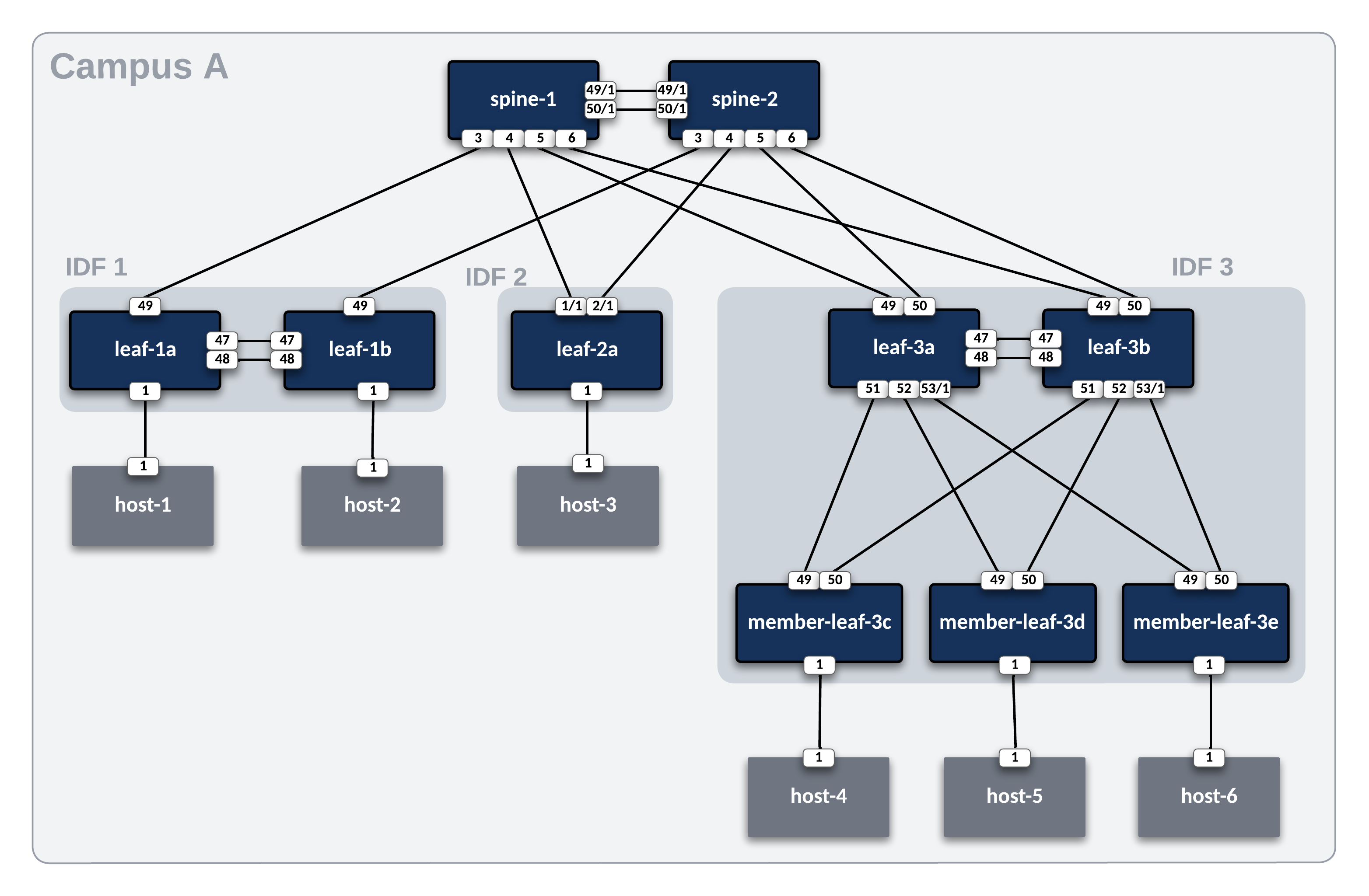
In this example, the ATD lab is used to create the L2LS campus center topology below.
Host Addresses
Since this workshop is for deploying and operating a campus style fabric, we have some endpoint hosts masquerading as VoIP phones.
| Host | IP Address | PC/Phone |
|---|---|---|
| host-1 | 10.1.10.101 | PC |
| host-2 | 10.1.20.101 | Phone |
| host-3 | 10.2.10.101 | PC |
| host-4 | 10.3.10.101 | PC |
| host-5 | 10.3.20.101 | Phone |
| host-6 | 10.100.100.102 | PC |
Step 1 - Prepare Lab Environment
Access the ATD Lab
Connect to your ATD Lab and start the Programmability IDE. Next, create a new Terminal.
Fork and Clone branch to ATD Lab
An ATD Campus L2LS data model is posted on GitHub.
- Fork this repository to your own GitHub account.
- Next, clone your forked repo to your ATD lab instance.
Configure your global Git settings.
Update AVD
AVD has been pre-installed in your lab environment. However, it may be on an older version (in some cases a newer version). The following steps will update AVD and modules to the valid versions for the lab.
Important
You must run these commands when you start your lab or a new shell (terminal).
Change To Lab Working Directory
Now that AVD is updated, lets move into the appropriate directory so we can access the files necessary for this Campus L2LS Lab!
Prepare Test Hosts
The last step in preparing your lab is to push pre-defined configurations to the six hosts used to test traffic. The hosts have various connection modes to the leaf pairs and are pre-configured with an IP address and route to reach the other hosts.
Run the following to push the configs.
Enable CloudVision Campus Features
For this workshop, some of the Campus related features and functionality we want to use are still being developed, so we will need to manually enable them.
We will want to enable the following. Please contact your SE or ATD Leader if you need assistance:
- Campus Beta Features
- Campus Network Hierarchy
Step 2 - Build and Deploy Campus L2LS Network
This section will review and update the existing Campus L2LS data model. We will add features to enable VLANs and SVIs which will complete our underlay infrastructure. After the lab, you will have enabled an L2LS Campus network through automation with AVD. YAML data models and Ansible playbooks will be used to generate EOS CLI configurations and deploy them to each site.
Summary of Steps
- Create CloudVision Service Account for AVD
- Build and Deploy
Campus A - Check campus hierarchy view and import changes to studios
- Create endpoint port profiles in CloudVision
- Configure leaf endpoint interfaces via Access Interface Configuration quick action
- Test traffic
Step 1 - Setup CloudVision Service Account Token
First, we will create our CloudVision Service Account and its associated token so we can talk to CloudVision with AVD, so we will want to launch our CloudVision instance from the ATD main dashboard.
CloudVision Service Account Documentation
The official instructions here CloudVison documentation website. The token is used to connect to the CloudVision APIs when using the arista.avd.cv_deploy role.
-
To access the
Service Accountcreation area, first click Settings (gear icon), in the bottom left corner of CloudVision.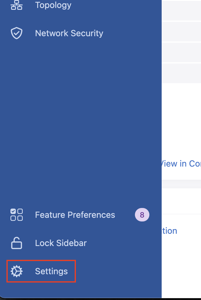
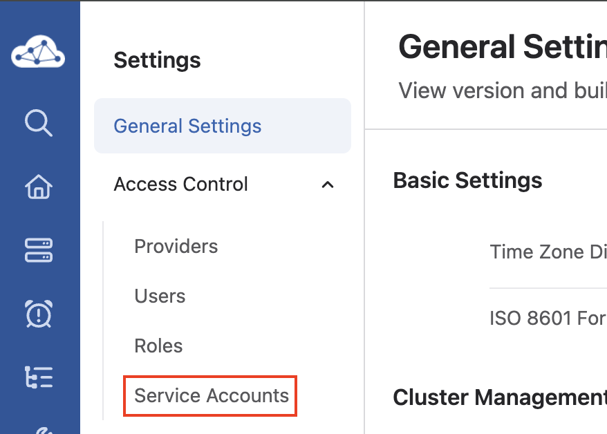
-
Next, click Service Accounts listed underneath the Access Control item,
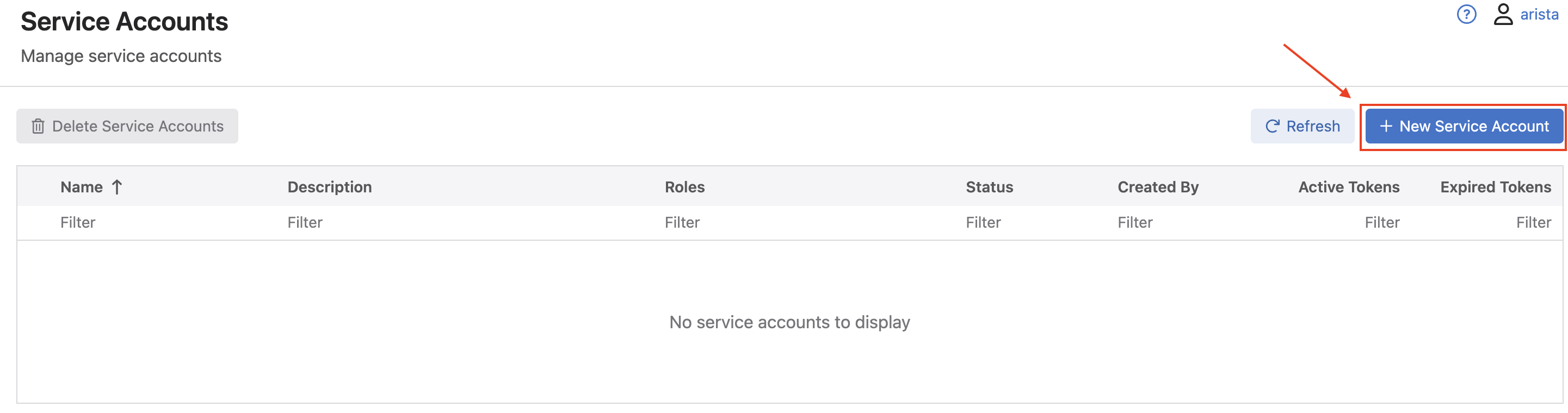
-
Once in the Service Accounts menu area, click the New Service Account button.
-
In the New Service Account window that pops up, fill in a
service account name,description(these can be any name or description you choose), select the drop down list for Roles, and selectnetwork-admin, and click Create.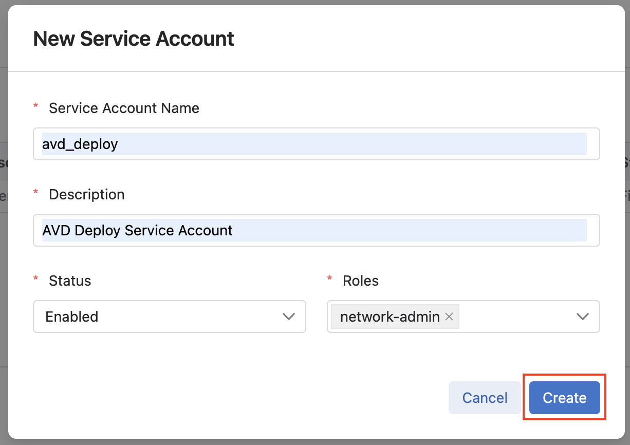
-
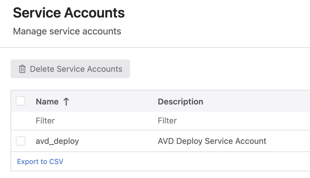
You should then be taken back to the main Service Accounts list, where you should see an account listed with the name and description you gave it in the previous step.
-
Next, click the name of your service account, which should open the Edit Service Account window. Under the Generate Service Account Token area, add a
Description, and select the calendar icon to pick aValid Untildate, and finally click Generate.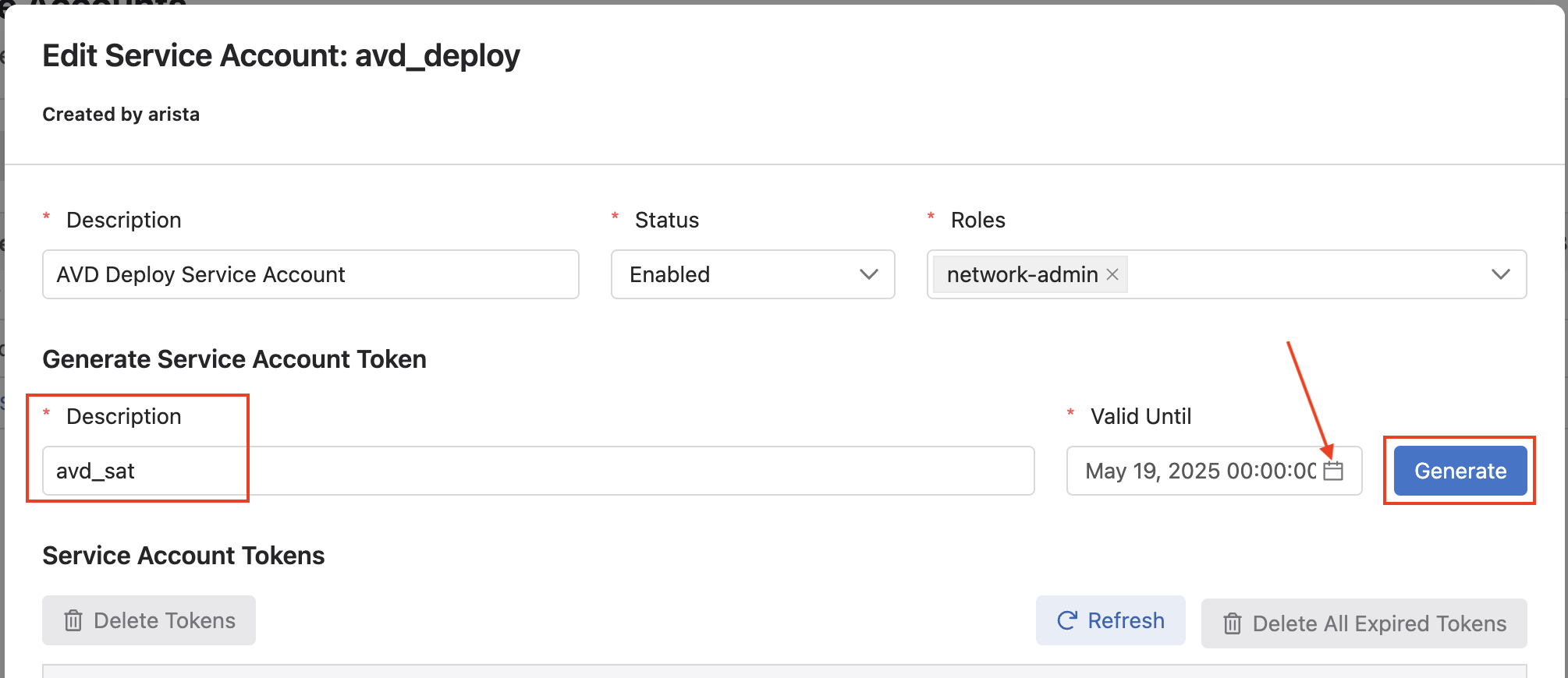
-
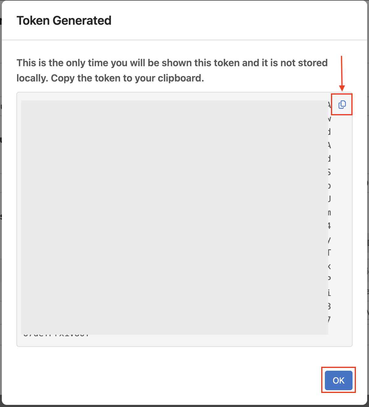
After clicking Generate, a new window will open with your service account token. We need to save this token as an environment variable. Our
global_campus_vars.ymlfile is configured to look for theCV_TOKENenvironment variable to be set as thecv_tokenAVD variable.# arista.avd.cv_deploy role parameters # Export token using 'export CV_TOKEN=<generated token here>' cv_token: "{{ lookup('env', 'CV_TOKEN') }}"Click the clipboard icon to easily copy the entire token, and then paste the key in your terminal with the following:
Note
We set the token as an environment variable for basic security. In a production environment, we recommend leveraging Ansible Vault.
After exporting the environment variable, go back to CloudVision and click OK on the token screen.
-
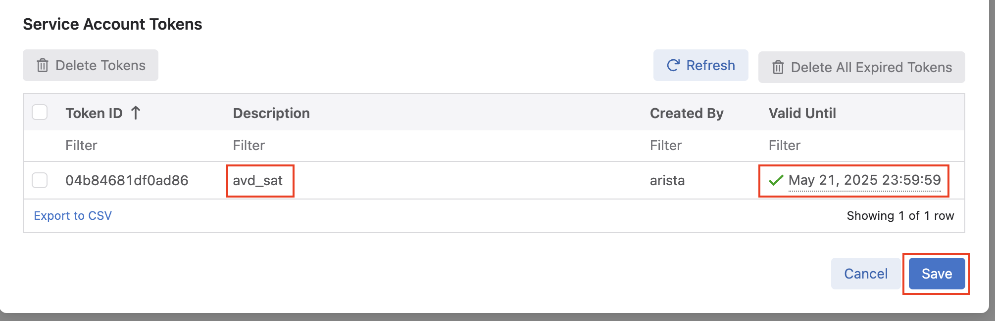
Finally, after clicking Ok, you will be back at the Edit Service Account window, where you should see a token listed matching the description and validity date you set. Click Save to save the token.
Step 2 - Build and Deploy Initial Fabric
The initial fabric data model key/value pairs have been pre-populated in the following group_vars files in the sites/campus_a/group_vars/ directory.
- CAMPUS_A_FABRIC.yml
- CAMPUS_A_SPINES.yml
- CAMPUS_A_LEAFS.yml
- CAMPUS_A_NETWORK_SERVICES.yml
Review these files to understand how they relate to the topology above.
At this point, we can build and deploy our initial configurations to the topology.
Note
Feel free to run git add and git commit to create a snapshot of the current build state. This will help you view the differences between steps in the workshop..
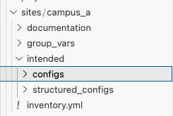
AVD creates a separate markdown and EOS configuration file per switch. In addition, you can review the files in the documentation and intended folders per site.
Now, deploy the configurations to the Campus A switches.
Since we are using CloudVision to deploy all of our changes we will need to jump into Provisioning and check out what's happening.
First, we want to check that the workspace with our changes has been submitted and is either closed or in the process of being closed.
In CloudVision, browse to Provisioning -> Workspaces. There, you should see in either Other Open Workspaces or Closed Workspace, a workspace with the name AVD (date)(timestamp), with your service account name you created, similar to the image below:
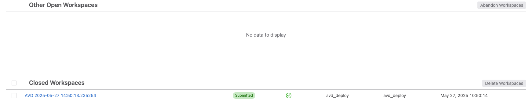
At this point, we don't need to interact with the workspace at all. AVD automatically creates the workspace with our changes, and submits it for us. If you want to view the details of our configuration changes and what was submitted, you can click the workspace name to open it.
Now that the workspace has been closed, we need to approve and execute our changes using the CloudVision Change Control process.
From within the same Provisioning menu, click on the Change Control sub menu. Here, we should see a pending Change Control. with the name AVD (date)(timestamp), that says (created by workspace).
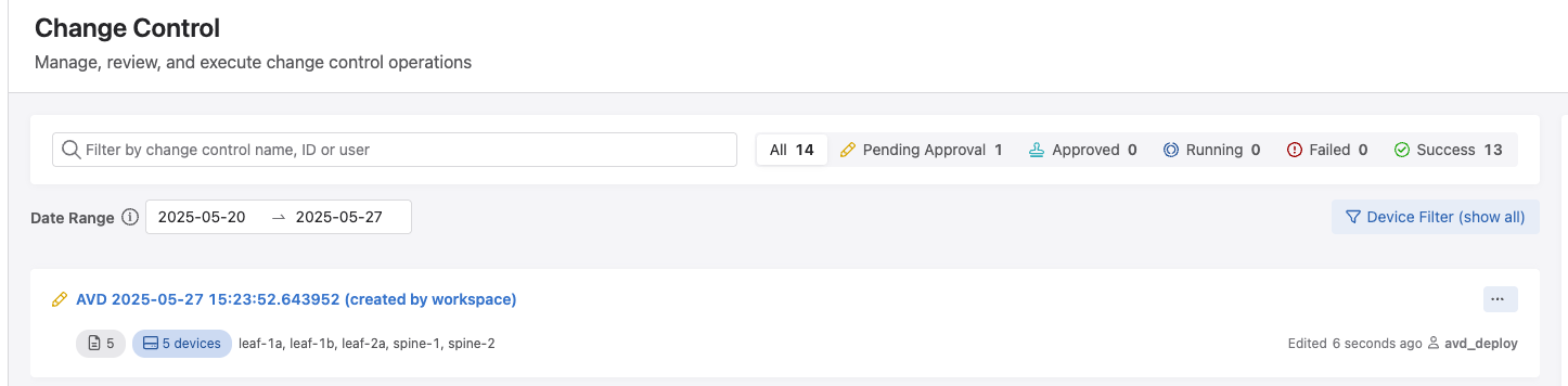
Click the new change control, where you can view the details of it, such as the affected devices, and then click Review and Approve.
Once the Review Change window opens, we can see the details of the AVD rendered configuration changes we are deploying to our switches.
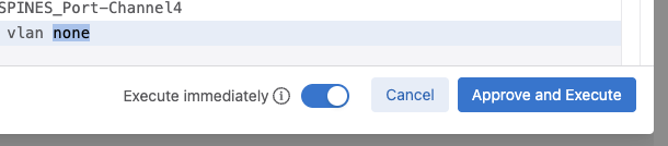
Finally, we will want to click the slider in the bottom right to Execute Immediately, and then click Approve and Execute.
Login to your switches to verify the current configs (show run) match the ones created in intended/configs folder.
You can also check the current state for MLAG, VLANs, interfaces, and port-channels.
The basic fabric with MLAG peers and port-channels between leaf and spines are now created. Next up, we will add VLAN and SVI services to the fabric.
Step 3 - Add Services to the Fabric
The next step is to add Vlans and SVIs to the fabric. The services data model file CAMPUS_A_NETWORK_SERVICES.yml is pre-populated with Vlans and SVIs for the campus fabric.
Open CAMPUS_A_NETWORK_SERVICES.yml and uncomment lines 1-72, then run the build & deploy process again.
Tip
 In VS Code, you can toggle comments on/off by selecting the text and pressing windows Ctrl + / or mac Cmd + /.
CV Deploy
After running the deploy command with AVD, remember to hop back into CloudVision and approve and execute the associated change control.
Log into spine-1 and spine-2 and verify the SVIs 110, 120, 210, 220, 310, and 320 exist.
It should look similar to the following:
spine-1#sho ip int brief
                                                                                Address
Interface         IP Address            Status       Protocol            MTU    Owner
----------------- --------------------- ------------ -------------- ----------- -------
Ethernet1         10.100.0.1/31         up           up                 1500
Loopback0         10.1.252.1/32         up           up                65535
Management0       192.168.0.12/24       up           up                 1500
Vlan110           10.1.10.2/24          up           up                 1500
Vlan120           10.1.20.2/24          up           up                 1500
Vlan210           10.2.10.2/24          up           up                 1500
Vlan220           10.2.20.2/24          up           up                 1500
Vlan310           10.3.10.2/24          up           up                 1500
Vlan320           10.3.20.2/24          up           up                 1500
Vlan4093          10.1.253.2/31         up           up                 1500
Vlan4094          10.1.253.0/31         up           up                 1500
We can also verify the correct VLANs are being trunked to the appropriate leafs.
It should look similar to the following:
spine-1#sho int trunk
Port            Mode            Status          Native vlan
Po3             trunk           trunking        1
Po4             trunk           trunking        1
Po5             trunk           trunking        1
Po491           trunk           trunking        1

Port            Vlans allowed
Po3             110,120
Po4             210,220
Po5             310,320
Po491           All

Port            Vlans allowed and active in management domain
Po3             110,120
Po4             210,220
Po5             310,320
Po491           1,110,120,210,220,310,320,4093-4094

Port            Vlans in spanning tree forwarding state
Po3             110,120
Po4             210,220
Po5             310,320
Po491           1,110,120,210,220,310,320,4093-4094
You can verify the recent configuration session was created.
Info
When the configuration is applied via a configuration session, EOS will create a "checkpoint" of the configuration. This checkpoint is a snapshot of the device's running configuration as it was prior to the configuration session being committed.
List the recent checkpoints.
View the contents of the latest checkpoint file.
See the difference between the running config and the latest checkpoint file.
Tip
This will show the differences between the current device configuration
and the configuration before we did our make deploy command.
Step 4 - Check Campus Network Hierarchy
Now that we have our base configurations built with AVD and deployed with CloudVision, we want to check out the Campus Network Hierarchy view to see what details that gives us, so we can move our operational functionality of endpoint port assignment into the CloudVision Access Interface Configuration quick action Studio.
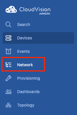
First, lets check out the Campus Network Hierarchy IDF view. In the left CloudVision menu, click on Network.
From here, we should see an overview of our newly deployed campus fabric. Click on Campus A to expand out that campus and we can then see the outcome of one of the main benefits with using AVD to render the configs, and that's the tagging function that enables the hierarchy view we are currently seeing.
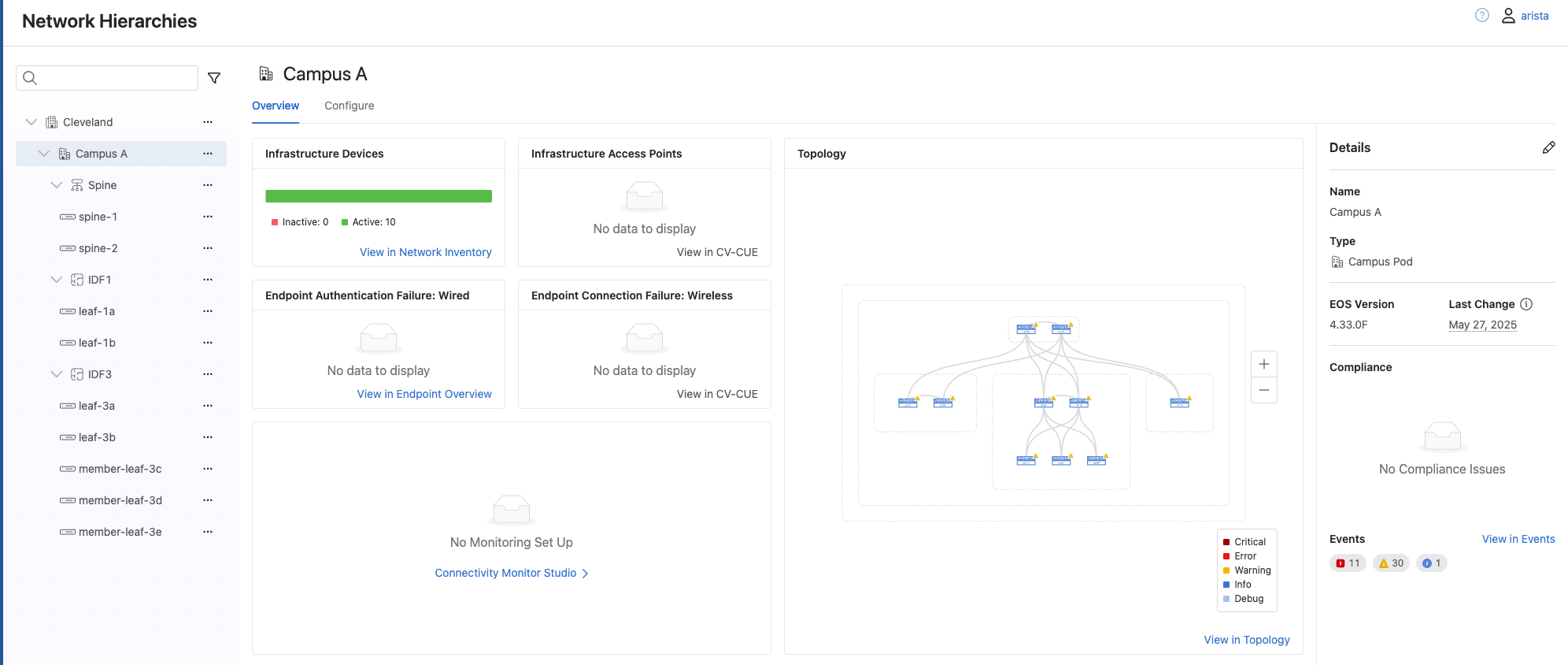
Take some time to click around and explore all the information that is available in this view.
While we are looking around, we can notice something missing, IDF2. While it shows up in the main topology view, we don't see its own nested level in the hierarchy. For now we will ignore this as we will come back to fix it during our day 2 operations.
Access Interface Quick Action
Now that we have reviewed the IDF view, lets look at the Access Interface quick action we will use to quickly configure our endpoint ports.
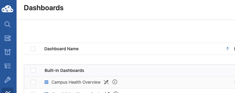
To get here, select Dashboards from the side menu, then select the built in Campus Health Overview.
In the bottom left corner, we will see a Quick Actions section. Here we will click Access Interface Configuration.
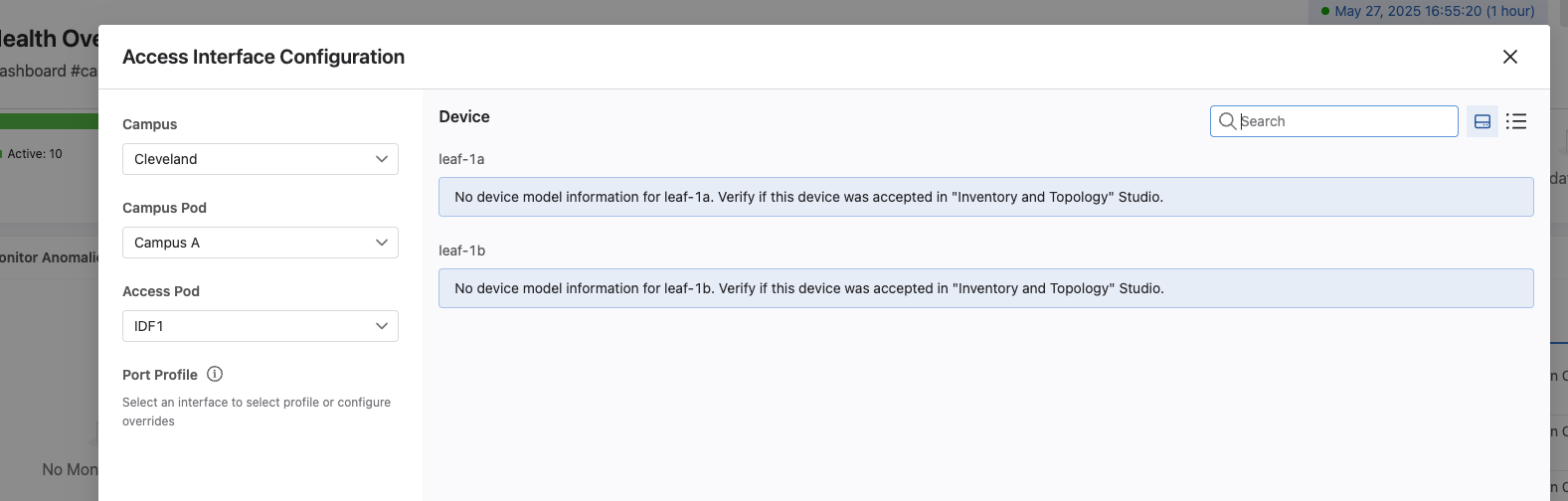
Next, lets select our Campus, Cleveland, our Campus Pod, Campus A, and an IDF, IDF1.
After selection these items, we will see we are unable to load the information about our devices. This is because the first time we load configuration items from AVD through CloudVision, we must accept them in the CloudVision Inventory and Topology studio.
Lets accept our updates so our campus fabric will be in a complete state and ready to accept any changes via AVD and the Quick Actions studio.
From the main CloudVision left hand menu, select Provisioning, and then select Studios.
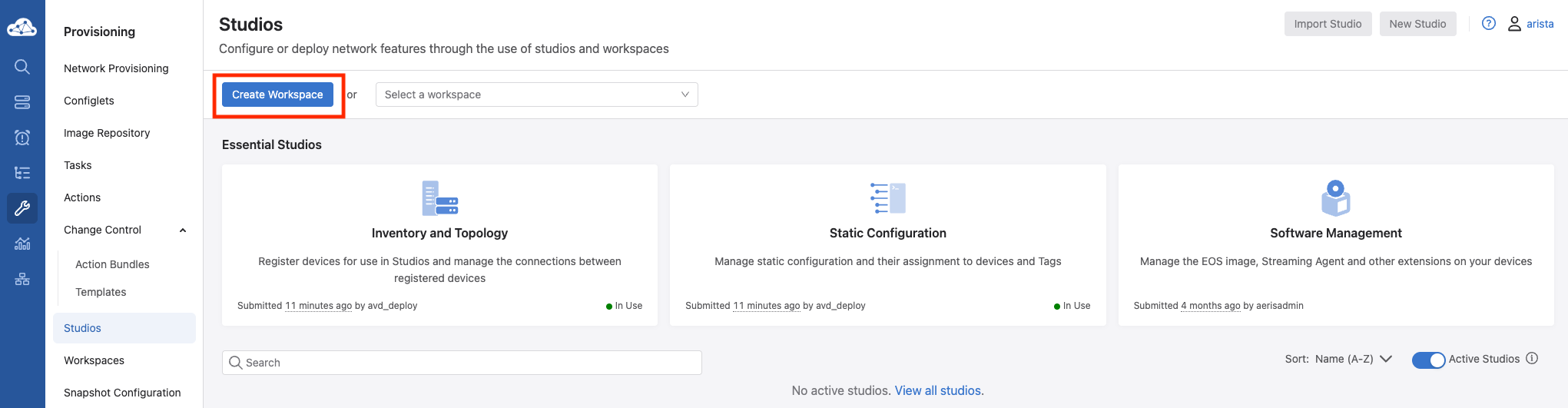
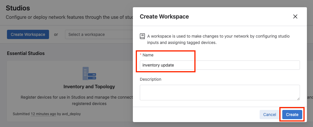
From here, we will want to create a new workspace so we can make changes. Click the Create Workspace button, give it a name, and click Create.
From the main Studios screen, we will select the Inventory and Topology studio to modify.
Once in the Inventory and Topology studio, select the Network Updates tab, then select the box next to Update to select all the updates, then select Accept Updates, and select Accept. Finally, select Review Workspace in the upper right corner.
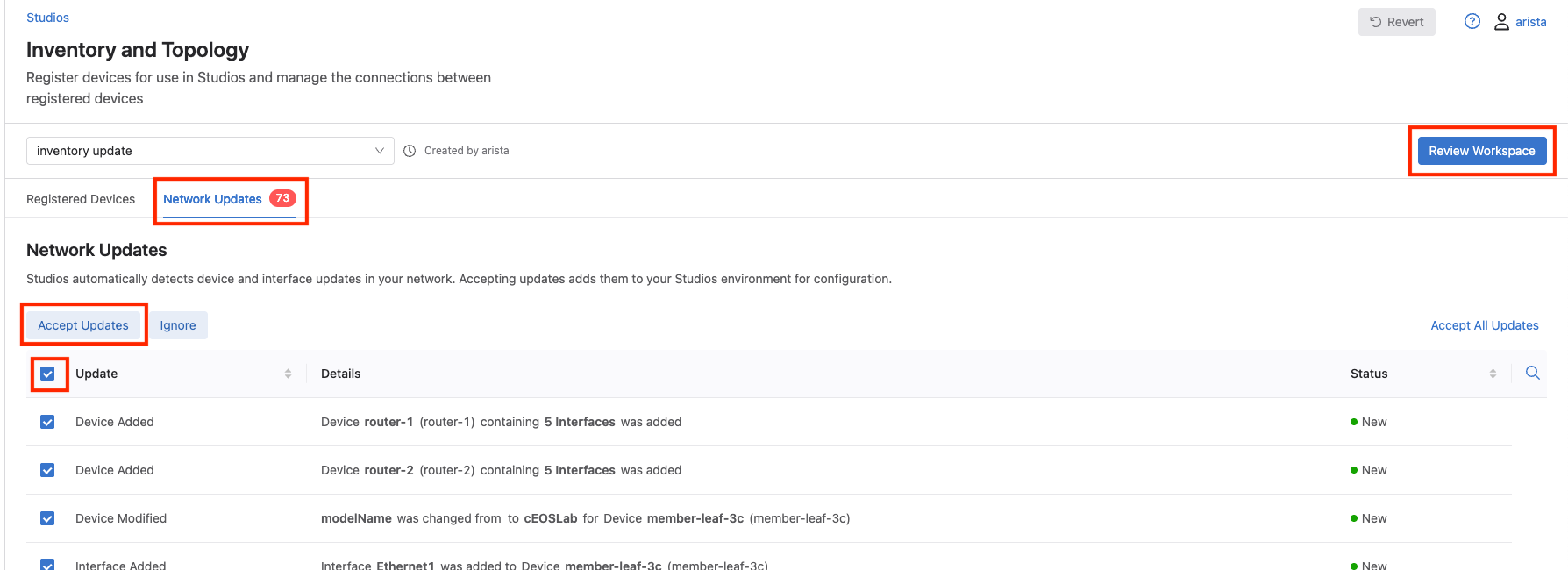
In the workspace review screen we should see no proposed configuration changes, and an all successful build status. Then select Submit Workspace.
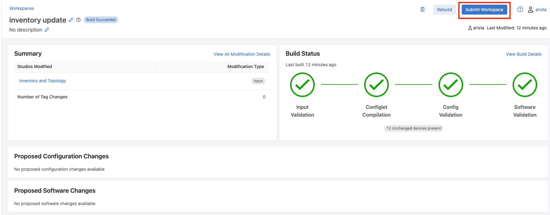
Since no configuration changes are made, there will be no change control created, so we can just click Close on the Workspace Submitted pop up window.
Now we can move back over to the Access Interface Configuration quick action and see if our device information is populated.
Select Dashboards from the side menu. In the bottom left corner, we will see a Quick Actions section. Here we will click Access Interface Configuration.
Again, lets select our Campus, Cleveland, our Campus Pod, Campus A, and an IDF, IDF1.
At this point, we should see our two leafs, leaf-1a and leaf-1b. If we click on one of the endpoint ports, such as port 1, we are shown the ability to quickly configure the port. However, before we can do that, we will need to complete one last step, and that's creating port profiles to use.
Lets click Cancel to back out of the Access Interface Configuration section so we can create our port profiles.
Step 5 - Create Port Profiles and Configure Endpoints
In order to be able to configure our endpoint ports on our leafs with the Quick Action studio, we need to create port profiles in studios as well.
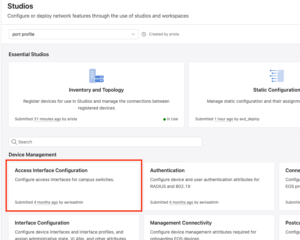
To do this, we will go back into Studios by selecting Provisioning from the main CloudVision menu, then selecting Studios.
Click Create Workspace, and give your workspace a name. Once in our workspace, click the Access Interface Configuration studio.
Here you will notice a few things.
1) Quick Actions - We can see this is assigned to the Access Interface Configuration quick action we are trying to work with.
2) Campus - We can see this is assigned to our Cleveland campus. If we had multiple tagged items, they would show up here.
Lets create our first port profile by clicking Add Port Profile.
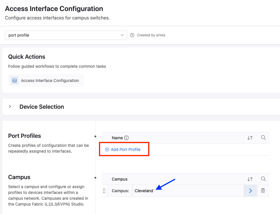
After clicking, the Add Port Profile button will move down and show a blank box to create our port profile and edit its properties. To create our first port profile, we can call it Access Port, and then click the right arrow to modify it.
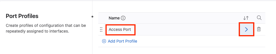
Some of these fields can be configured here in the studio, or dynamically when we go through Access Interface Configuration. The only thing we will want to set here is Spanning Tree Portfast - edge.
Take some time to review everything that can be configured here.
Then, select Review Workspace in the upper right corner, then Submit Workspace to submit our changes.
Now we can move back over to the Access Interface Configuration quick action to configure our endpoints.
Select Dashboards from the side menu. In the bottom left corner, we will see a Quick Actions section. Here we will click Access Interface Configuration.
Again, lets select our Campus, Cleveland, our Campus Pod, Campus A, and an IDF, IDF1.
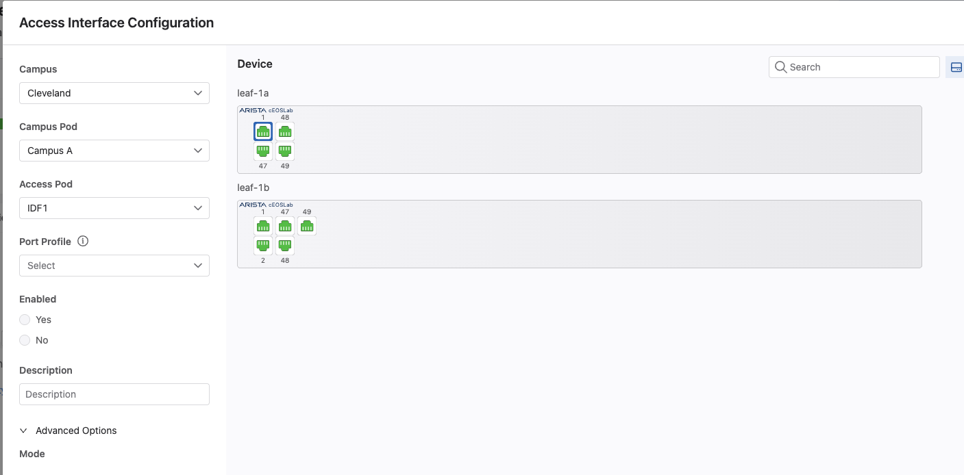
Select leaf-1a port 1, so we can configure host-1.
We will select the Access Port port profile from the drop down list. Check the Yes bubble under Enabled. In the Description field, we can enter host-1.
Next, expand out Advanced Options, set the Mode to access, and VLANs to 110.
After completing, select the Review button to review our proposed configuration changes.
Here we should see our new configuration changes. Finally, click Confirm to push our changes out.
Repeat the above steps for host-2, host-4, and host-5, setting them in the VLANs defined below:
-
host-2- Connects on
leaf-1b, Ethernet1 - VLAN 120
- Connects on
-
host-4- Connects on
member-leaf-3c, Ethernet1 - VLAN 310
- Connects on
-
host-5- Connects on
member-leaf-3d, Ethernet1 - VLAN 320
- Connects on
Step 6 - Test Traffic
At this point, hosts in IDF1 and IDF3 should be able to ping each other across the fabric as well as to their default gateways.
From host-1, run a ping to its default gateway.
PING 10.1.10.1 (10.1.10.1) 72(100) bytes of data.
80 bytes from 10.1.10.1: icmp_seq=1 ttl=63 time=30.2 ms
80 bytes from 10.1.10.1: icmp_seq=2 ttl=63 time=29.5 ms
80 bytes from 10.1.10.1: icmp_seq=3 ttl=63 time=28.8 ms
80 bytes from 10.1.10.1: icmp_seq=4 ttl=63 time=24.8 ms
80 bytes from 10.1.10.1: icmp_seq=5 ttl=63 time=26.2 ms
From host-1, run a ping to host-2, which are on the same leaf pair, but in different subnets.
PING 10.1.20.101 (10.20.20.100) 72(100) bytes of data.
80 bytes from 10.1.20.101: icmp_seq=1 ttl=63 time=30.2 ms
80 bytes from 10.1.20.101: icmp_seq=2 ttl=63 time=29.5 ms
80 bytes from 10.1.20.101: icmp_seq=3 ttl=63 time=28.8 ms
80 bytes from 10.1.20.101: icmp_seq=4 ttl=63 time=24.8 ms
80 bytes from 10.1.20.101: icmp_seq=5 ttl=63 time=26.2 ms
From host-1, run a ping to host-5, which is on member-leaf-3d.
PING 10.3.20.101 (10.3.20.101) 72(100) bytes of data.
80 bytes from 10.3.20.101: icmp_seq=1 ttl=63 time=30.2 ms
80 bytes from 10.3.20.101: icmp_seq=2 ttl=63 time=29.5 ms
80 bytes from 10.3.20.101: icmp_seq=3 ttl=63 time=28.8 ms
80 bytes from 10.3.20.101: icmp_seq=4 ttl=63 time=24.8 ms
80 bytes from 10.3.20.101: icmp_seq=5 ttl=63 time=26.2 ms
Campus A fabric is now almost complete.
Great Success!
You have built a campus L2LS network without touching the CLI on a single switch!
Onto Day 2 Operations
Let's move onto Day 2 Operations where we will fix the issue with IDF2, as well as deploy new services.